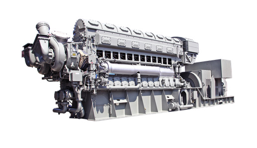
The Fairbanks Morse 38D8-1/8 is an inline, opposed-piston, two-stroke diesel engine renowned for its reliability and widespread application in U.S. Navy and U.S. Coast Guard vessels. This article will examine the overall design of the engine and its broad applications, as well as provide a specific instance of its use on a submarine.
Design

The numerical designation of the engine is derived from the design date and cylinder bore diameter. Introduced in 1938, these engines have been in continuous production since that time and are currently available through Fairbanks Morse’s successor, FMDefense. The bore measures 8 and 1/8 inches, with a stroke of 10 inches. Hence, 38D8-1/8.
According to the manufacturer, Fairbanks Morse Defense, the current specifications for the engines are as follows:
| Cylinder configuration | 6L, 9L, 12L |
| Bore | 8.1 in. |
| Stroke | 10 in. |
| Cycle | 2 stroke |
| Displacement/cylinder | 1,037 cu. in. |
| Mean piston speed | 25.0 ft./min. @ 900 rpm | 27.8 ft./min. @ 1,000 rpm |
| Fuel type | Diesel and Dual Fuel (Natural Gas + Diesel Pilot) |
Power Ratings
The engines have a power range of 1,566 – 3,628 kWb (1,169 – 2,707 bhp).2
| Cylinders | Aspiration | 50Hz 1,000RPM kWe / 60Hz 900RPM kWe3 |
|---|---|---|
| 6L | Turbo-blower | 1,506 |
| 6L | Turbocharged | 1,580 |
| 9L | Turbo-blower | 2,260 |
| 9L | Turbocharged | 2,370 |
| 12L | Turbo-blower | 3,013 |
| 12L | Turbocharged | 3,165 |
At various points, these engines have been available in 4, 5, 6, 8, 9 10, and 12-cylinder inline configurations.4
What’s the difference between a four-stroke & a two-stroke engine?
Every so often I encounter someone who vehemently, albeit idiotically, tries to argue with me that there’s no such thing as a two-stroke engine. Whatever this person’s (claimed) credentials are, it’s pretty clear that they haven’t done their homework. While I’m no engineer, I can guarantee that they do, in fact, exist; the 38D8-1/8 is one such example. To prove my point, here’s an explanation of what the difference between a four-stroke and two-stroke engine is:
Four-Stroke: Operating principle employed in the majority of diesel (and petrol) engines. The four-stroke cycle commences with the induction stroke during which the piston moves from the top to the bottom of the cylinder and charge air is drawn or fed under pressure into the cylinder. During the compression stroke, the piston moves to the top of the cylinder, compressing the charge air. In a diesel engine, the fuel is injected and ignition commences fractionally before the piston reaches its top position. Then follows the power stroke during which fuel combustion occurs and the pressure of the expanding combustion gases forces the piston down the cylinder. Finally, during the exhaust stroke, the piston rises to the top of the cylinder, expelling the exhaust gases. The sequence has been succinctly and graphically described as “suck, squeeze, bang, blow.”
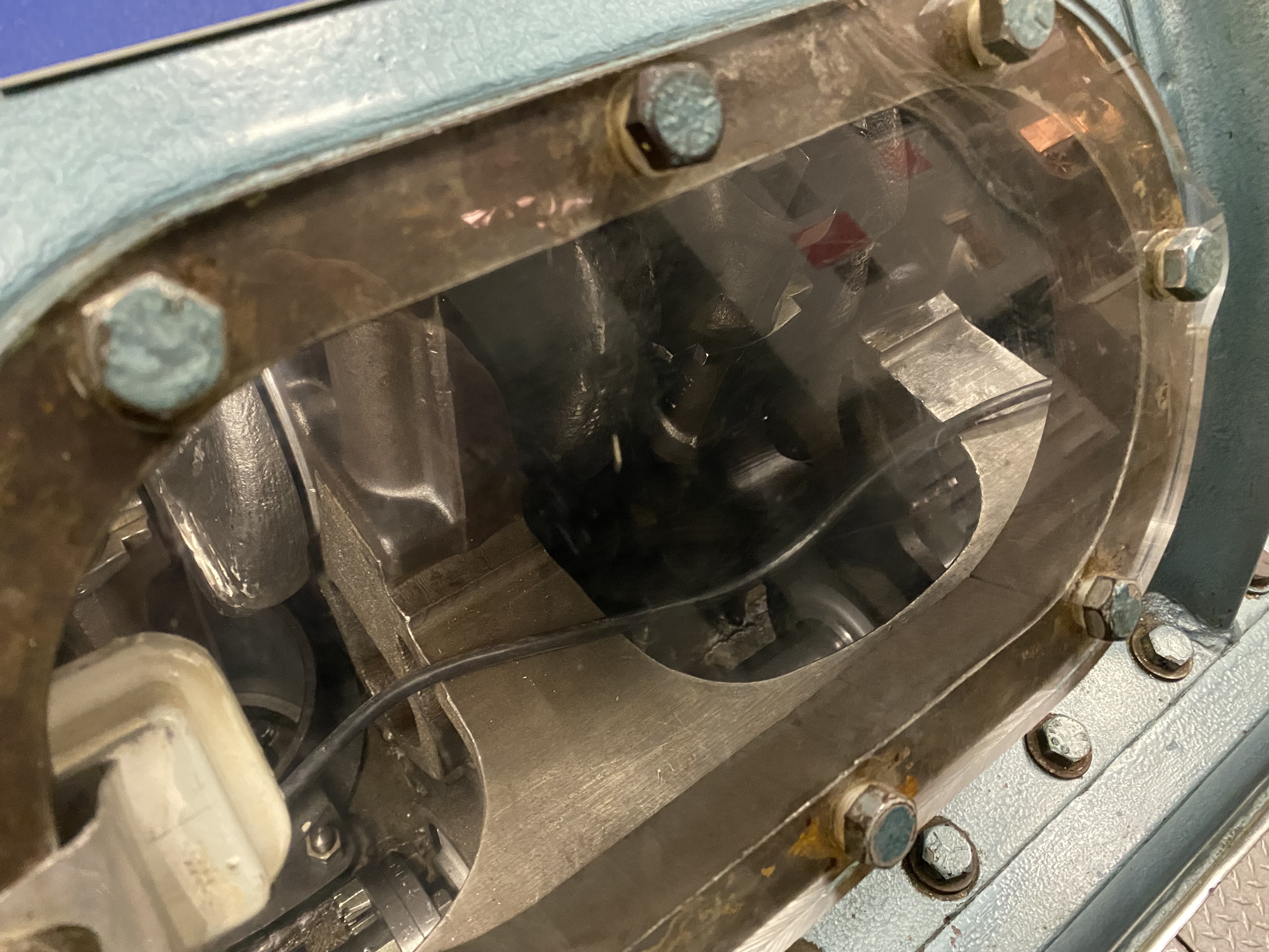
Two-Stroke: Operating principle employed in some very large ‘cathedral’ type marine propulsion diesels, some small model compression ignition engines, and some small petrol engines. The complete operating cycle occurs during only one revolution of the crankshaft, rather than the two revolutions required in a four-stroke engine. During the upward stroke of the piston, exhaust gases are blown out of the cylinder and the new charge of air is compressed. When the piston reaches the top of the cylinder, the engine begins its power stroke which ends with a fresh charge of air being inducted into the engine. Key advantages of the two-stroke are that one stroke in two is a power stroke (rather than the one in four of a four-stroke) and simplicity of construction with no valves or valve gear. Disadvantages are poor scavenging of exhaust gases after each power stroke and higher fuel consumption.5
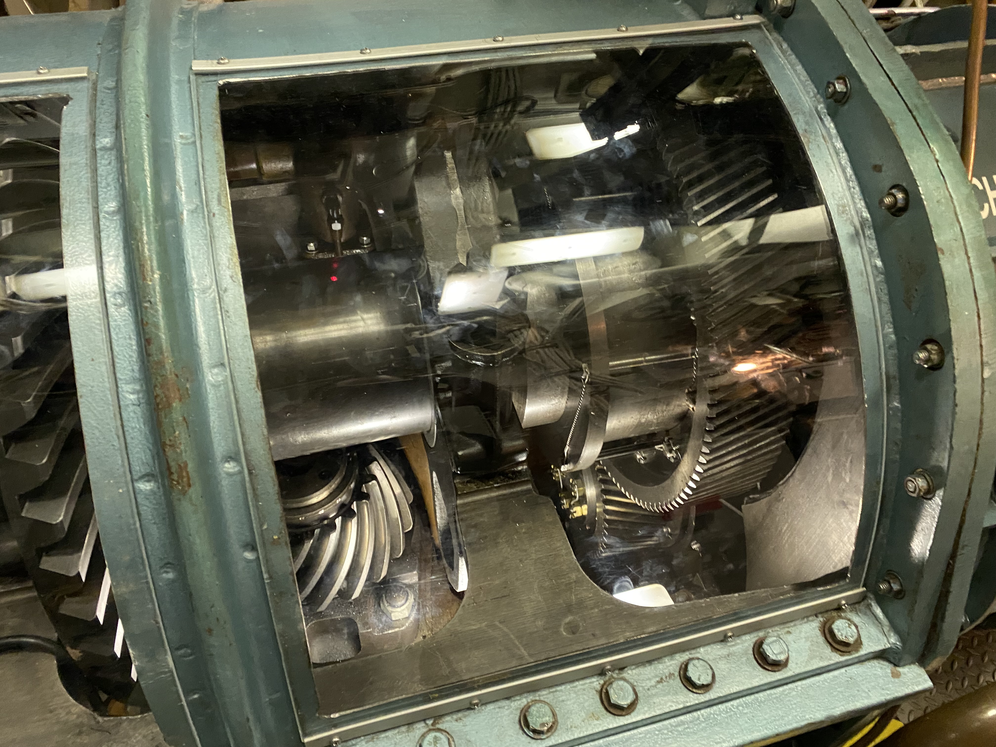
The following photo explains how the 38D8-1/8 engine operates:

Applications
Illustrative of the popularity of these engines, they are commonly used as marine, railway, and land-based power plants.
Note: The following are not exhaustive lists, but merely representative of where these engines could be found.
Marine
These engines were extensively used on U.S. Navy diesel-electric submarines during WWII and postwar. They were also used on many surface warships.
Submarine classes
| Tambor-class |  USS Tambor (SS-198) |
| Gato-class | 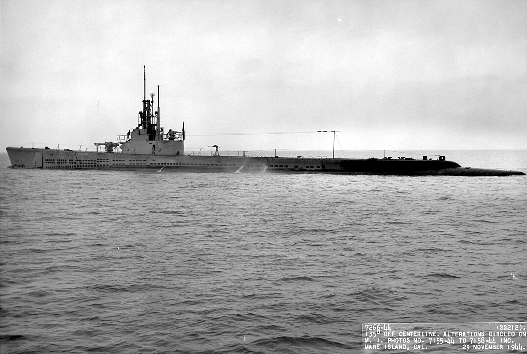 USS Gato (SS-212) |
| Balao-class | 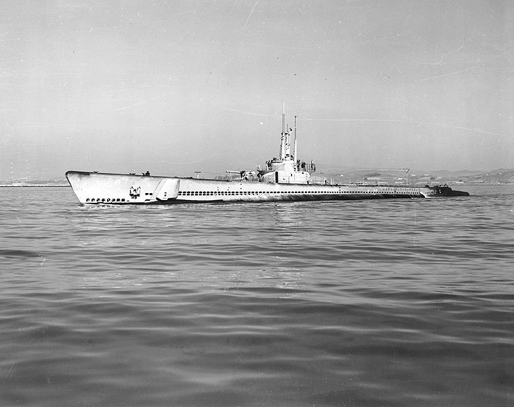 USS Balao (SS-285) |
| Tench-class |  USS Torsk (SS-432) |
| Grayback-class |  USS Grayback (SS/SSG/APSS/LPSS-574) |
| Tang-class |  USS Trigger (SS-564) |
| Sailfish-class |  USS Sailfish (SSR/SS/AGSS-572) |
| Barbel-class | 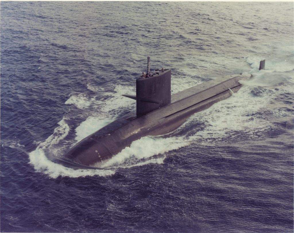 USS Barbel (SS-580) |
| Los Angeles-class *as an auxiliary diesel engine | 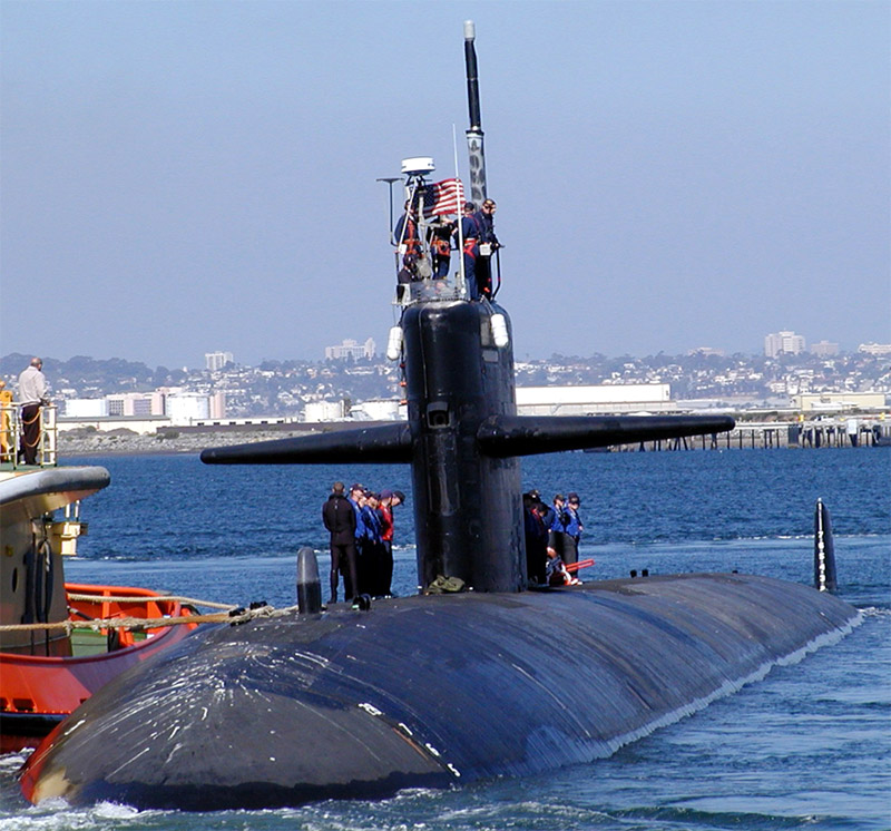 USS Bremerton (SSN-698) |
| Seawolf-class *as auxiliary diesel engine |  USS Seawolf (SSN-21) |
| Ohio-class *as an auxiliary diesel engine | 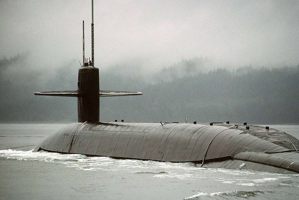 USS Ohio (SSBN/SSGN-726) |
Surface ship classes
| Edsall-class destroyer escorts | 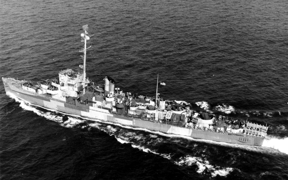 USS Edsall (DE-129) |
| U.S. Coast Guard Wind-class icebreakers | 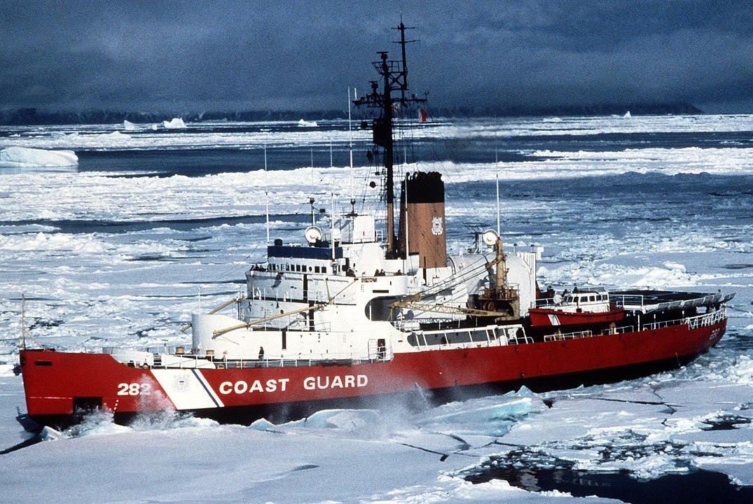 USCGC Northwind (WAG/WAGB-282) |
| USCGC Mackinaw (WAGB-83) (based on Wind-class design) |  |
| U.S. Coast Guard Hamilton-class high endurance cutters |  USCGC Rush (WHEC-723) |
Railroad
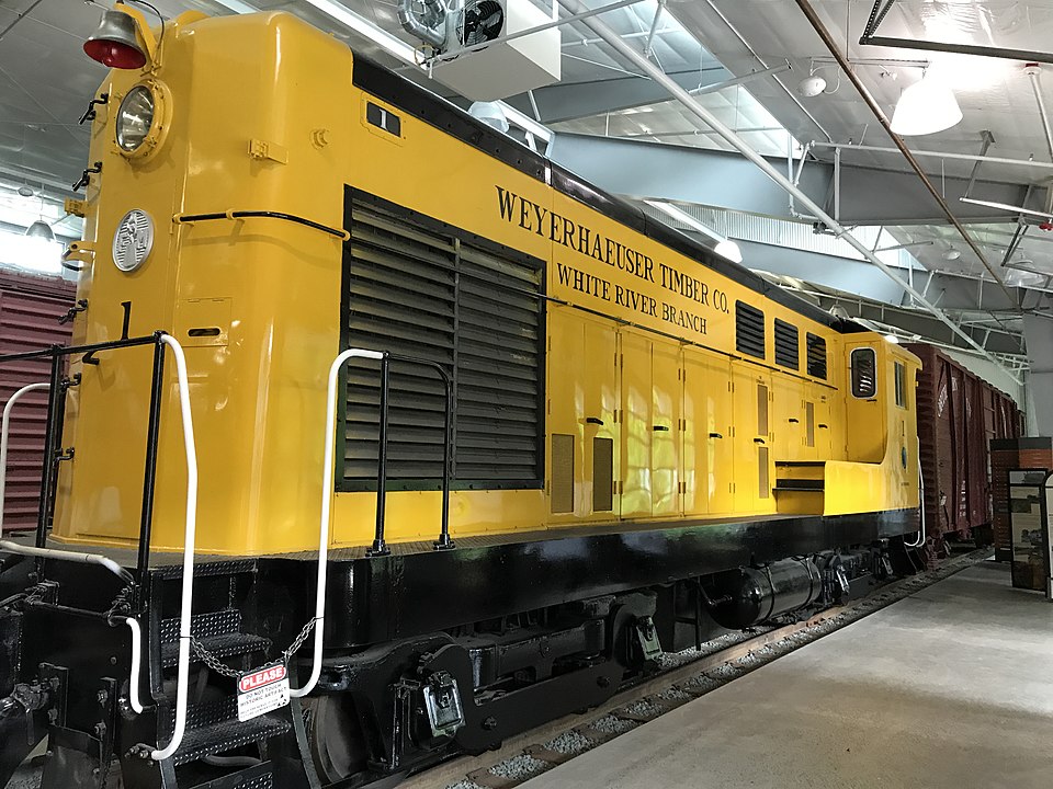
Starting in the 1940s, Fairbanks Morse began to market the engine to the railroad industry. They had some success with several designs, but overall, it seems that the opposed-piston design was not very well-suited for the stresses of locomotive operation and they ultimately proved to be maintenance intensive. This was particularly the case for those operating at high altitudes and in hot and dry climates. The company exited the locomotive market in 1963.
 H-10-44 |
 H-12-44 |
 H-20-44 |
 H-24-66 “Train Master” |
Land
The 38D8-1/8 can also be used as a stationary power generator.
A Diesel-Electric Submarine’s Main Power Equipment Characteristics
The remainder of this article will provide an example of the Fairbanks Morse 38D8-1/8 as it was used in a post-war diesel-electric submarine. We’ll examine the powerplant arrangements and general operation.
Following WWII, diesel-electric submarines in the U.S. Navy would undergo a further evolution in their performance characteristics with the capture of two Type XXI U-boats, U-2513 and U-3008. Based on the technology learned from the Type XXI U-boats, many surviving U.S. fleet boat-type submarines would undergo GUPPY (Greater Underwater Propulsion Program) conversions which included retrofitting them with more streamlined hulls and conning towers, as well as adding snorkels and improved batteries and fire control systems. The hull form of submarines would ultimately change with the experimental USS Albacore (AGSS-569) which introduced a teardrop (AKA body-of-revolution) type hull. This hull shape allowed for greater speed, maneuverability, and quieter operation while submerged. While the outer appearance would change, the essential workings of a diesel-electric submarine would remain the same.
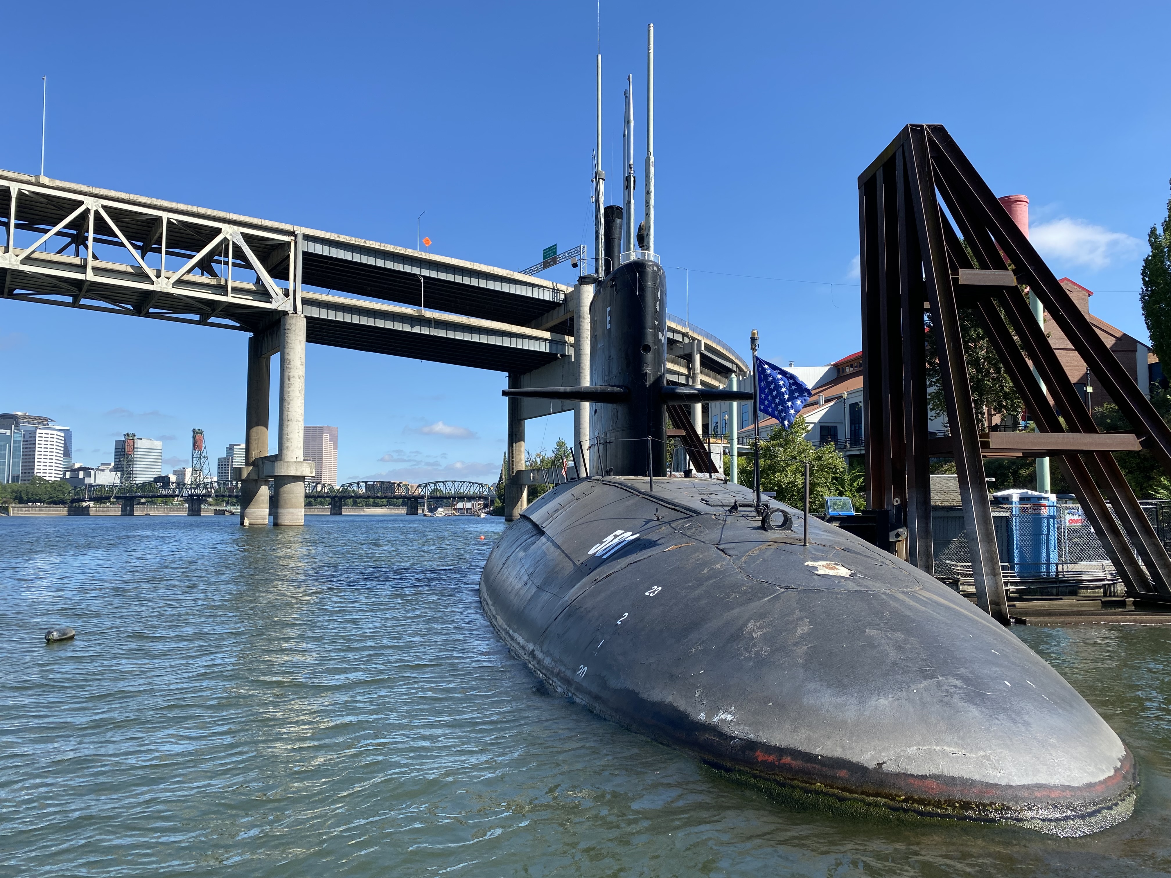
Based on the Albacore design, the Barbel-class submarines (USS Barbel (SS-580), USS Blueback (SS-581), and USS Bonefish (SS-582)) were the last class of conventional attack submarines in the U.S. Navy. Like the WWII fleet boats before them, the Barbels would also have Fairbanks Morse 38D8-1/8 diesel engines.
The following characteristics show the main powerplant arrangements of USS Blueback (SS-581). In commission from 1959 to 1990, she is the only surviving Barbel and the very last diesel-electric attack submarine in service with the U.S. Navy (aside from the research submarine USS Dolphin (AGSS-555)).
| Diesel Engines | 3x Fairbanks-Morse 38D8-1/8 | 2-stroke, 8-cylinder, 16 opposed piston | (Surfaced) 1,500 BHP at 850 RPM, 6200 CFM air (Snorkeling) 1,335 BHP at 800 RPM, 5850 CFM air |
| Generators | 3x General Electric | Commutating & Compensating Winding | 750 – 850 RPM, 940 KW, 545 – 710 volts 1,500 amps |
| Power Control | 1x Westinghouse Electric | Single Control | 545 volts (continuous) 710 volts (max) |
| Battery | 2x (252 cells each, in series) Gould | TLX 53 Open tank vent, water-cooled, agitated electrolyte | Ventilation 5,800 CFM total Underway charge 3,500 CFM total Submerged nominal volts 500 volts 1/2 hr. rate – 6,100 Amp hrs. 1 hr. rate – 4,000 Amp hrs. |
| Electric Motor | 1x General Electric | Direct drive, double armature MCF (commutating & compensating winding) | 212 RPM 6,440 shp 880 volts 2,975 Amps each armature 5,950 Amps total |
This arrangement also means that a diesel-electric submarine can only use its diesel engines when it’s on the surface or at snorkel depth. If the diesel engines were running when the submarine was submerged, they would draw air from inside the submarine and suffocate the crew with the diesel exhaust fumes instead of drawing air from the atmosphere. Blueback can carry 112,000 gallons of diesel fuel, which gives her a range of about 19,000 nm before needing refueling. If she was running at her top speed of roughly 21 knots submerged, the batteries would last about 35 minutes. However, at a slower speed of 4 knots, the batteries can last 105 hours (4.38 days).
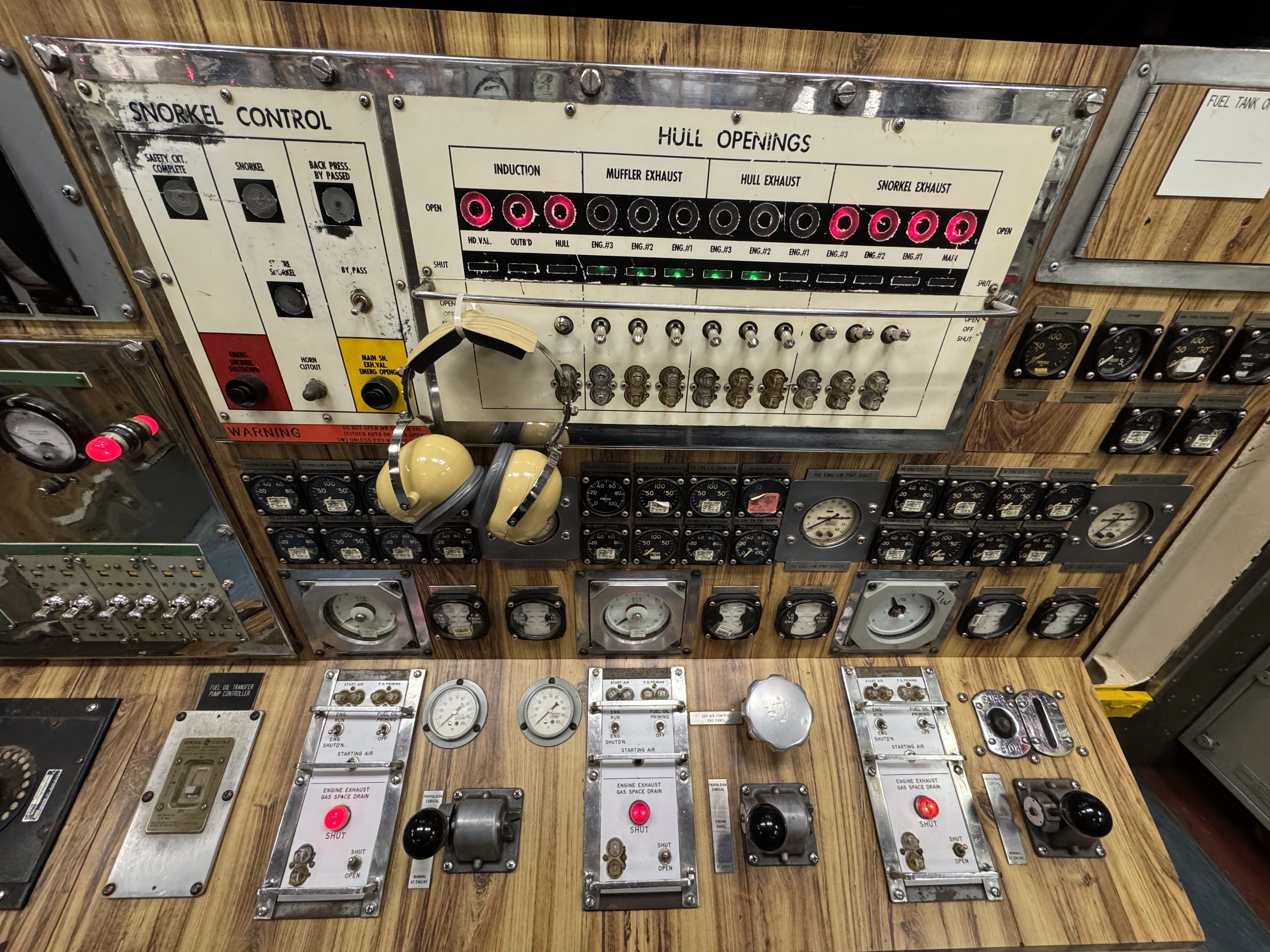
Snorkeling
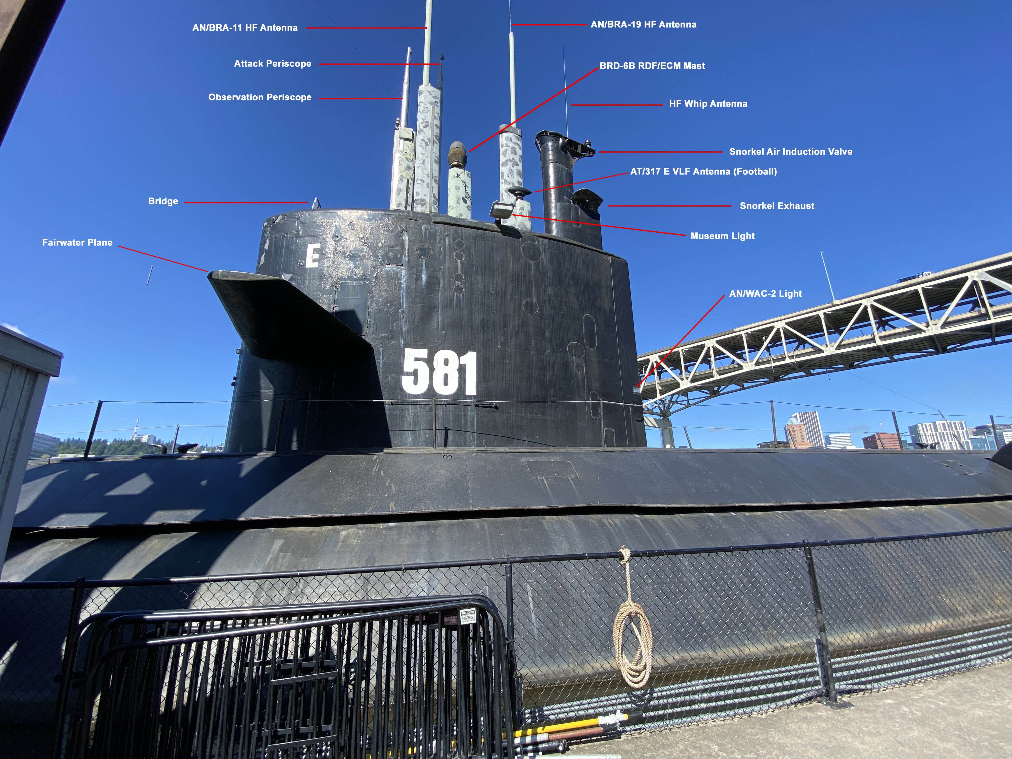
Like post-war conversions, the Barbel-class submarines also featured snorkels, which they could use down to about 59 feet. Blueback has a maximum operating speed of 14 knots when snorkeling. A former Navy quartermaster (who served on both Bonefish and Blueback) told me that, during normal operations, the submarine would ascend to snorkel depth every 2 – 3 days to recharge her batteries. If the batteries were fully drained, then it would take about 8 to 12 hours to charge them. He also related a story of how the submarine was operating off an “unnamed harbor” and gathering photographic intelligence with her periscopes. They would sneak in during the day and operate on battery power, then egress for the open ocean at night to charge batteries for about 8 hours. All three diesel engines could be run when snorkeling, but one of them would be shut down when the batteries were nearly charged just to conserve fuel.
Snorkeling would only be done at night when it would be harder to see the snorkel mast protruding from the water. Still, the quartermaster, handling navigation in the control room, would also need to know the time zone the submarine is in and the time of local sunset and sunrise. Woe betide the quartermaster who gets it wrong and has the submarine snorkel during daylight, thereby giving away its position.
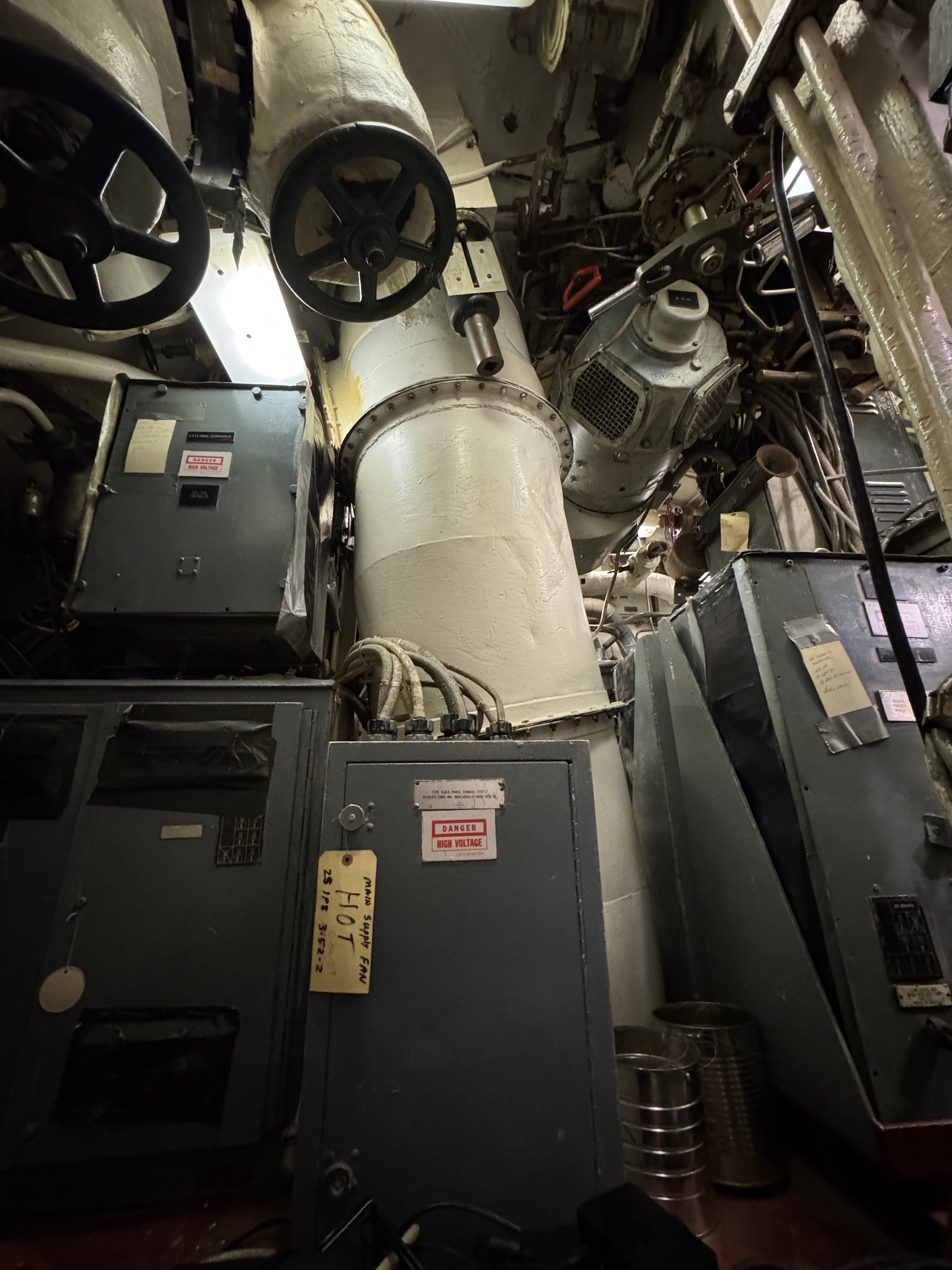
Blueback’s Engineering Spaces
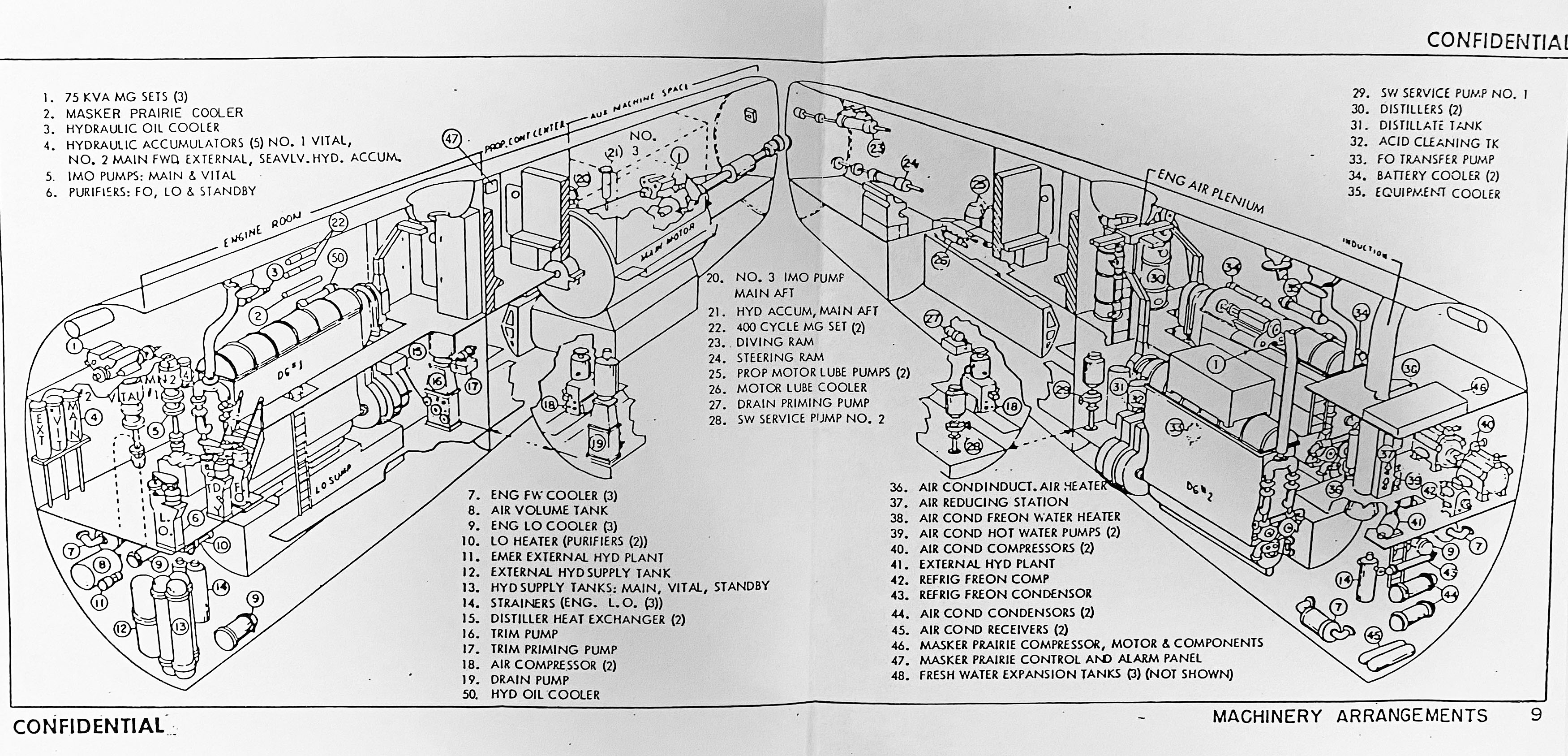
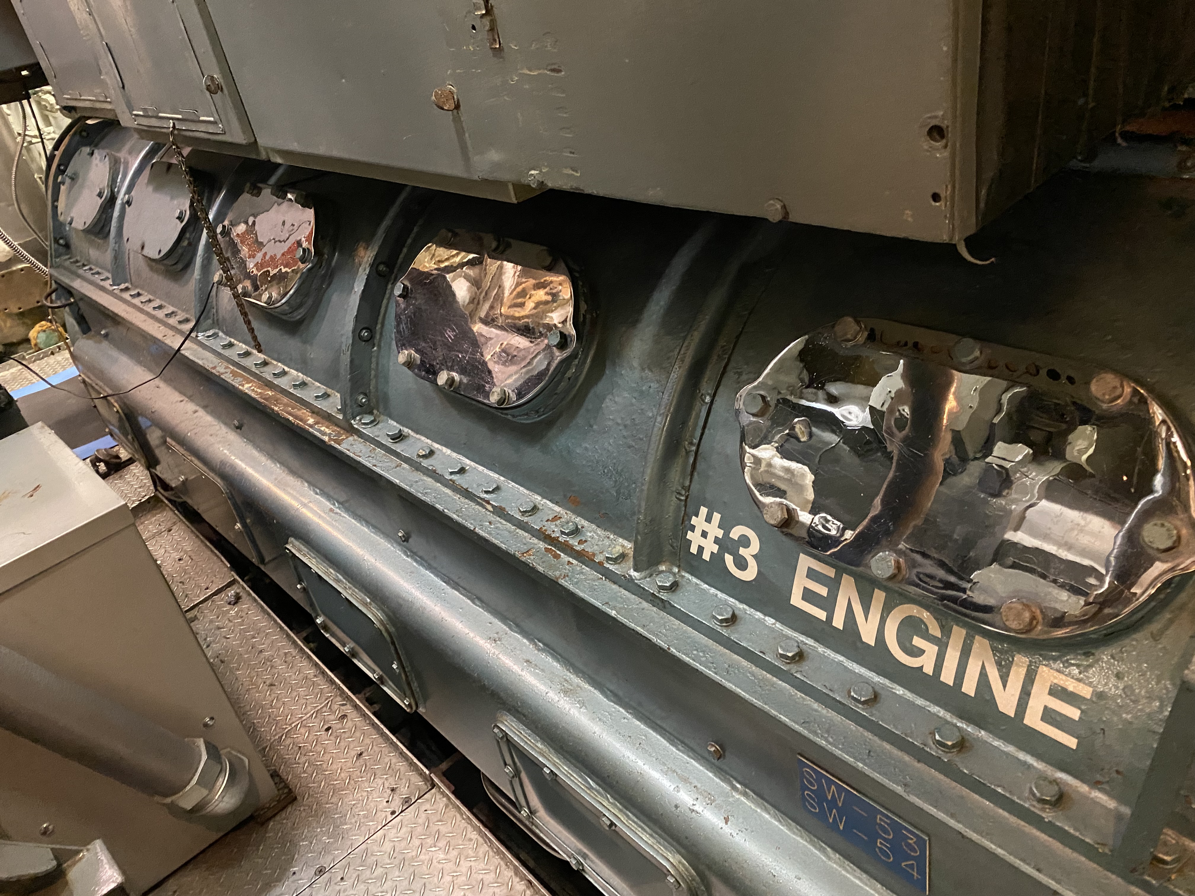
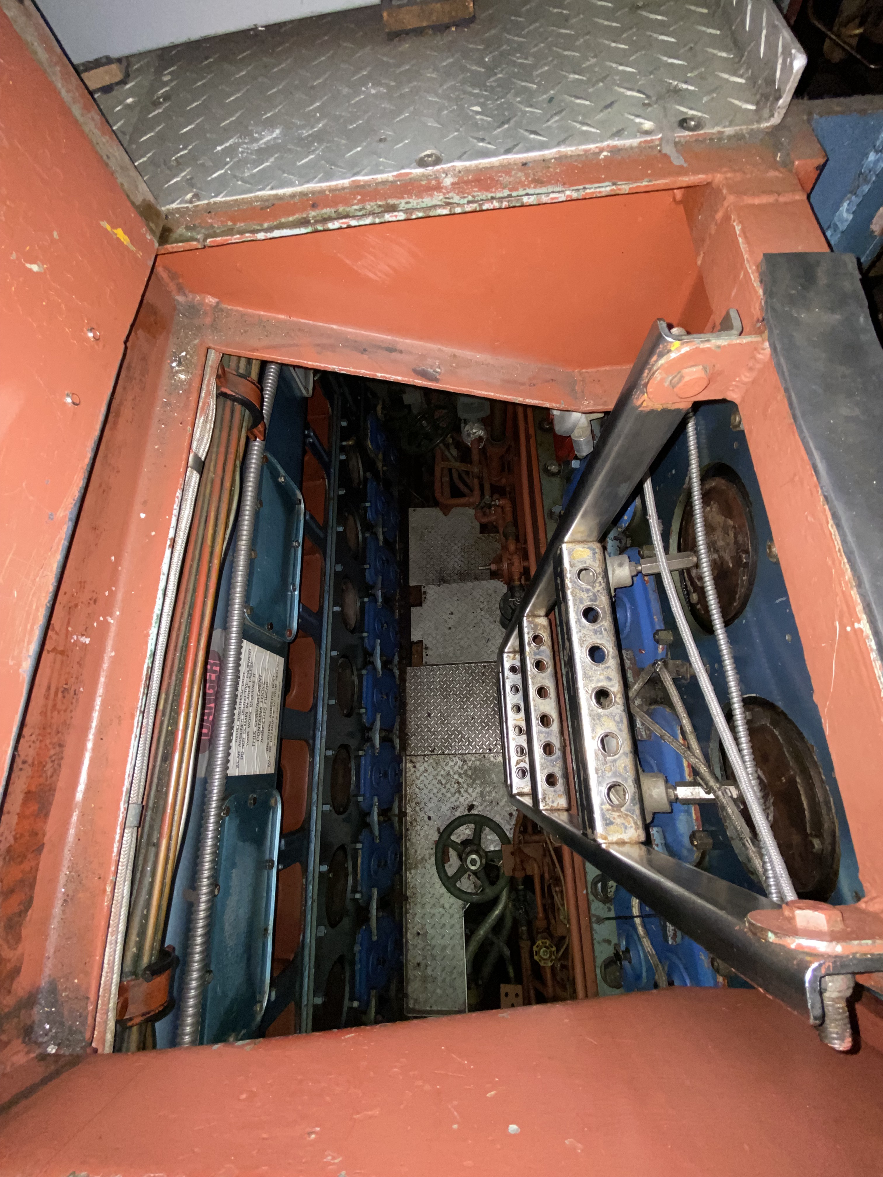
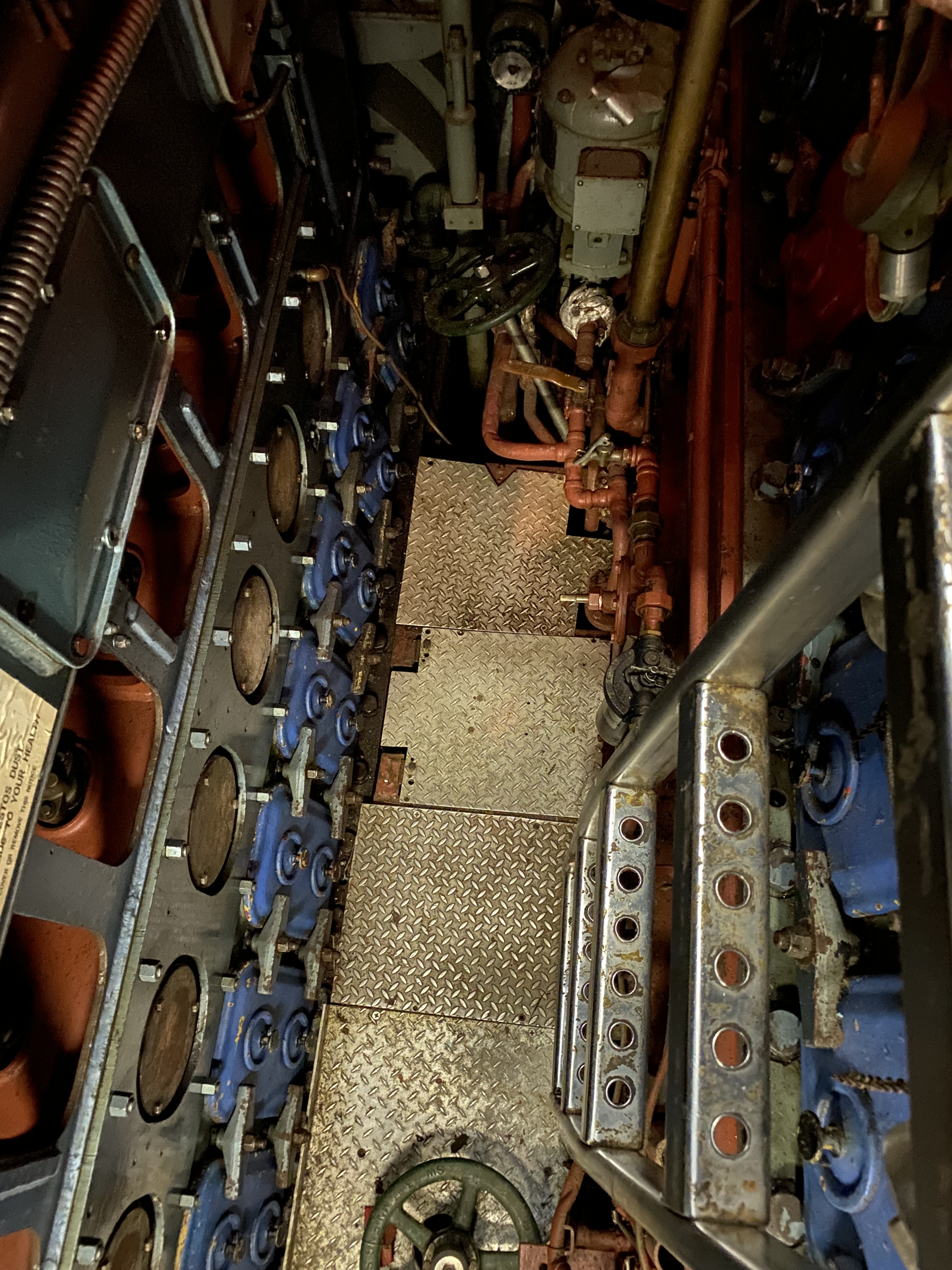
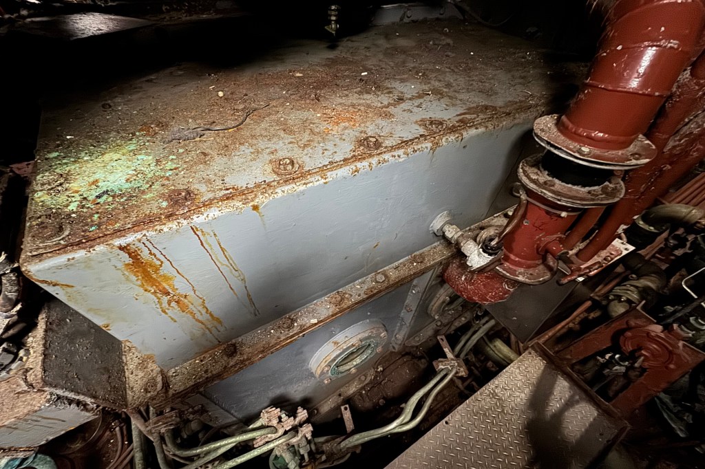
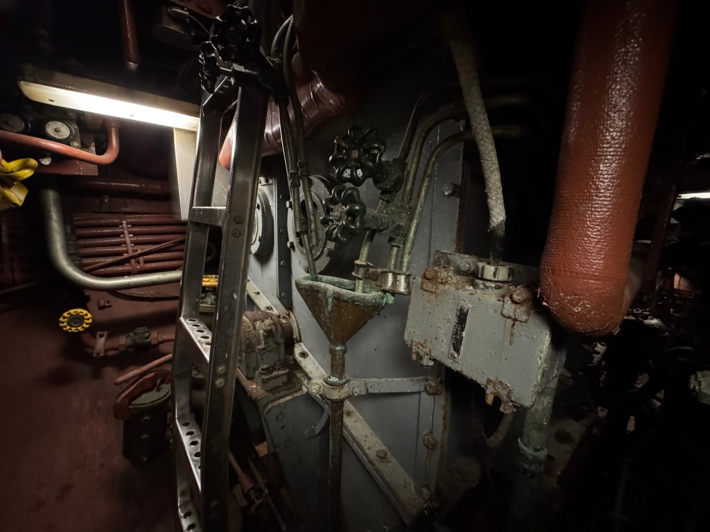
Engine Room
The engine room contains the three Fairbanks Morse 38D8 – 1/8 engines. These particular ones are of the 8-cylinder configuration, with each generating about 1,500 hp each. The engines are separated on two levels. Engines No. 1 and No. 3 are on the upper level, and Engine No. 2 is on the lower level which is accessible by hatches and vertical ladders in the deck plating. The engines are turned over with about 250 psi of air to start them.

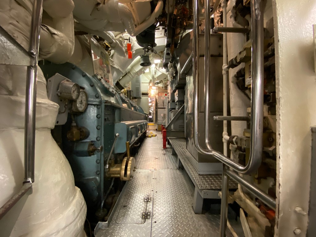
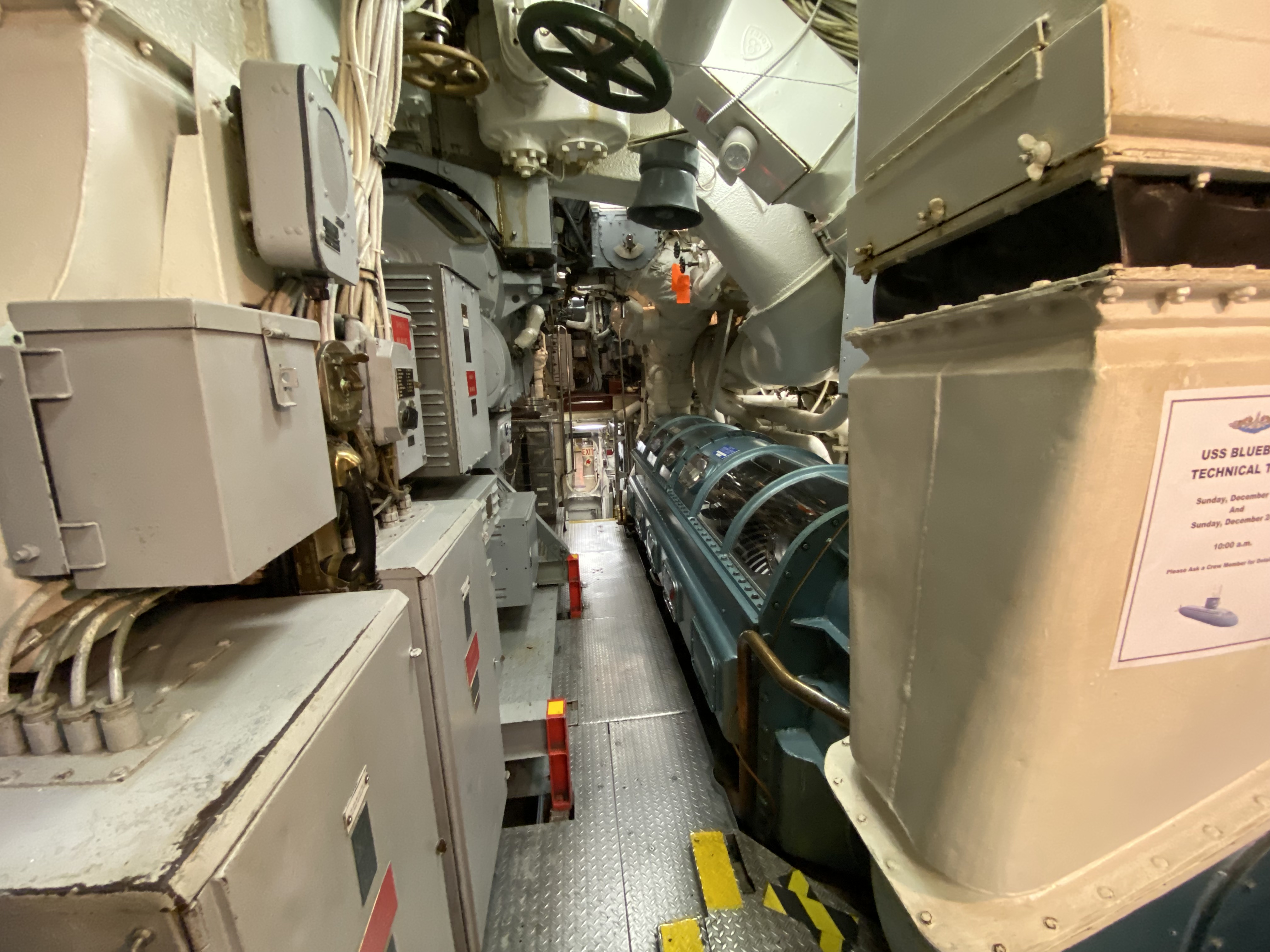
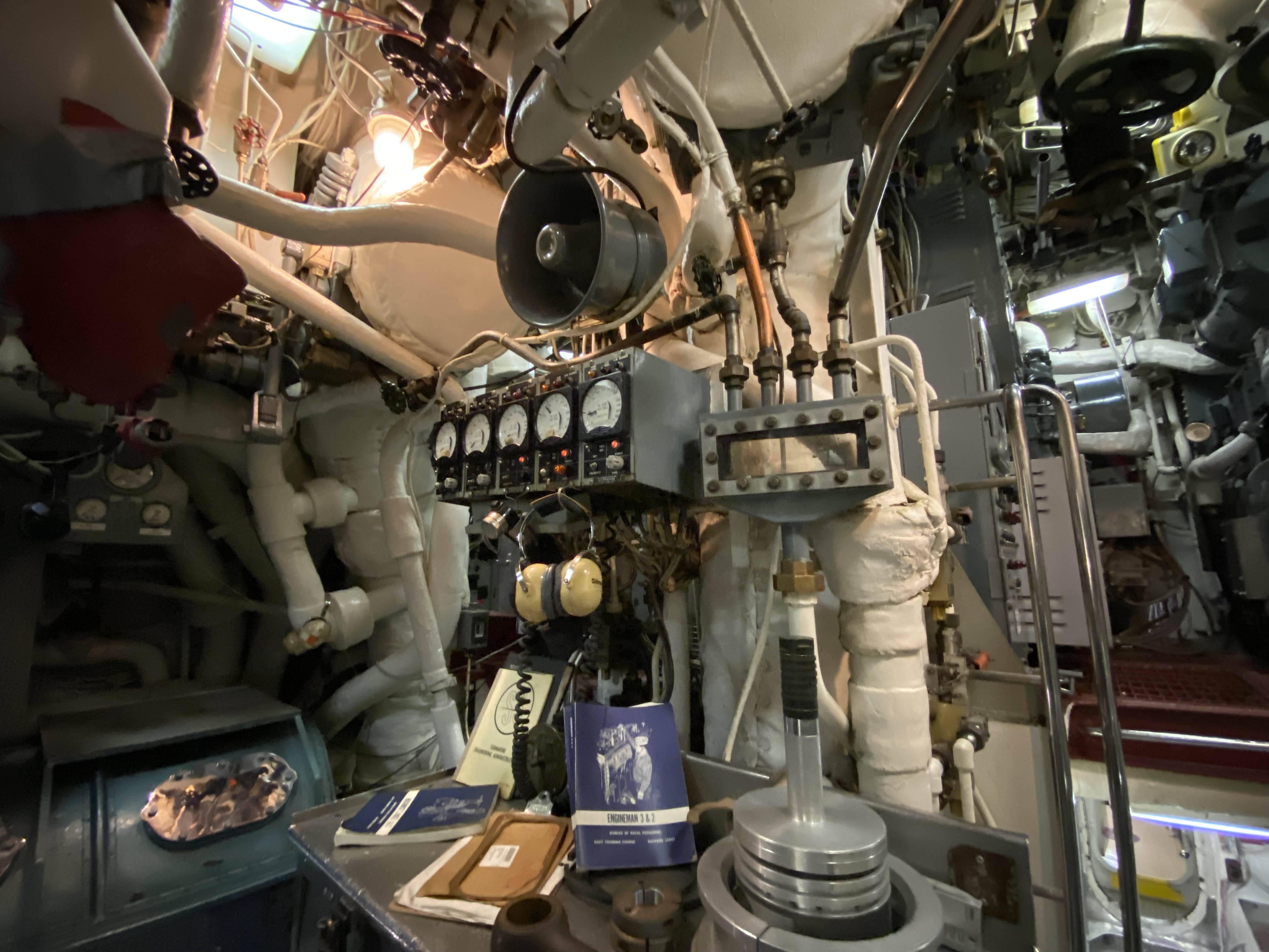
Visitors to Blueback will note that the engine room is rather noisy. That sound is actually a recording. In real life, if those engines were running, then they would purr at 137 dB, and the room would reach 120 – 130 degrees F. If you were to enter the engine room without hearing protection, you would have permanent hearing damage in 30 minutes. So you’d have to wear double the hearing protection. That means rubber earplugs and “Mickey Mouse” earmuffs.
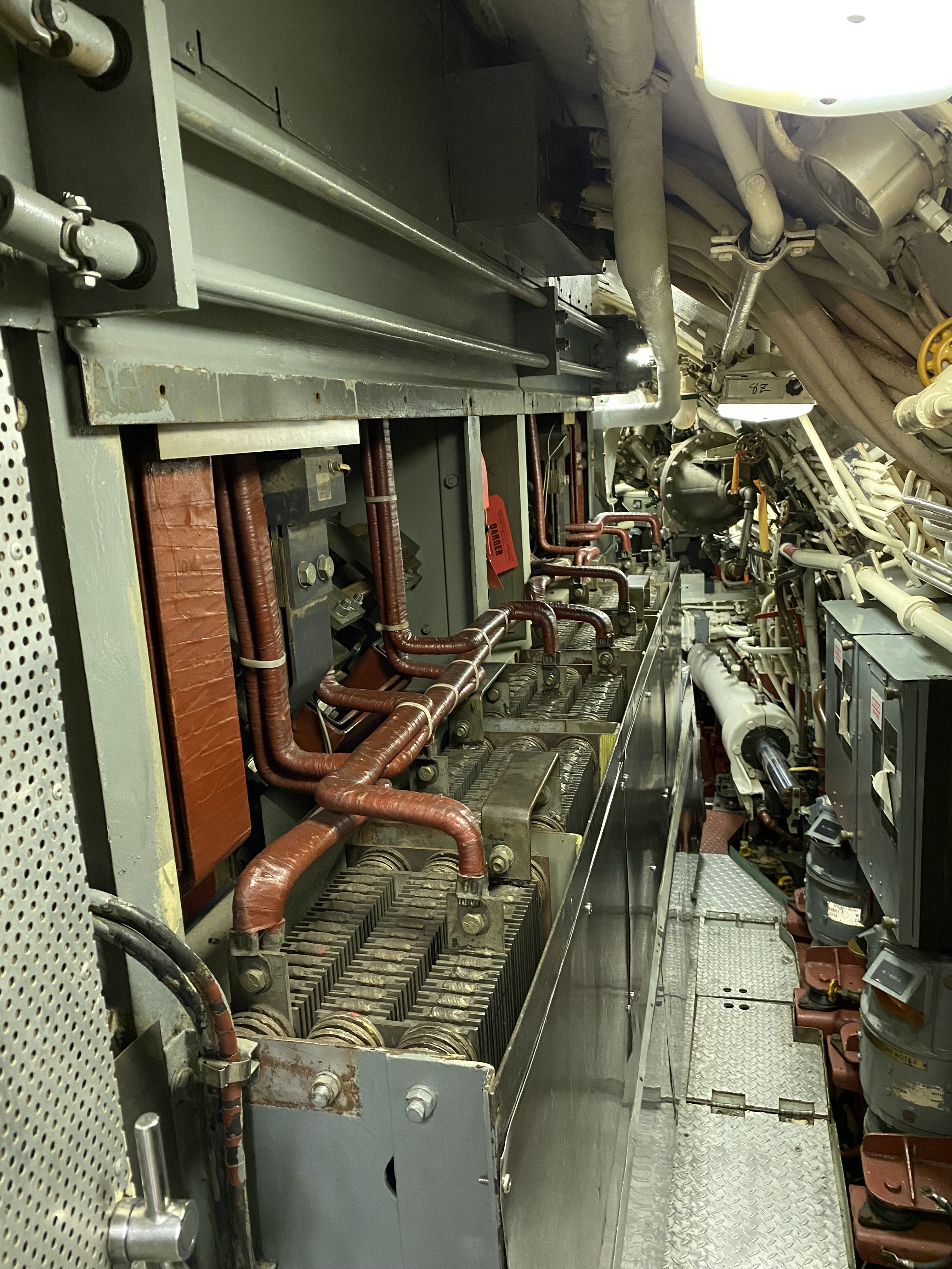
Maneuvering Room
Abaft of the engine room is the maneuvering room which controls all propulsion for the submarine.
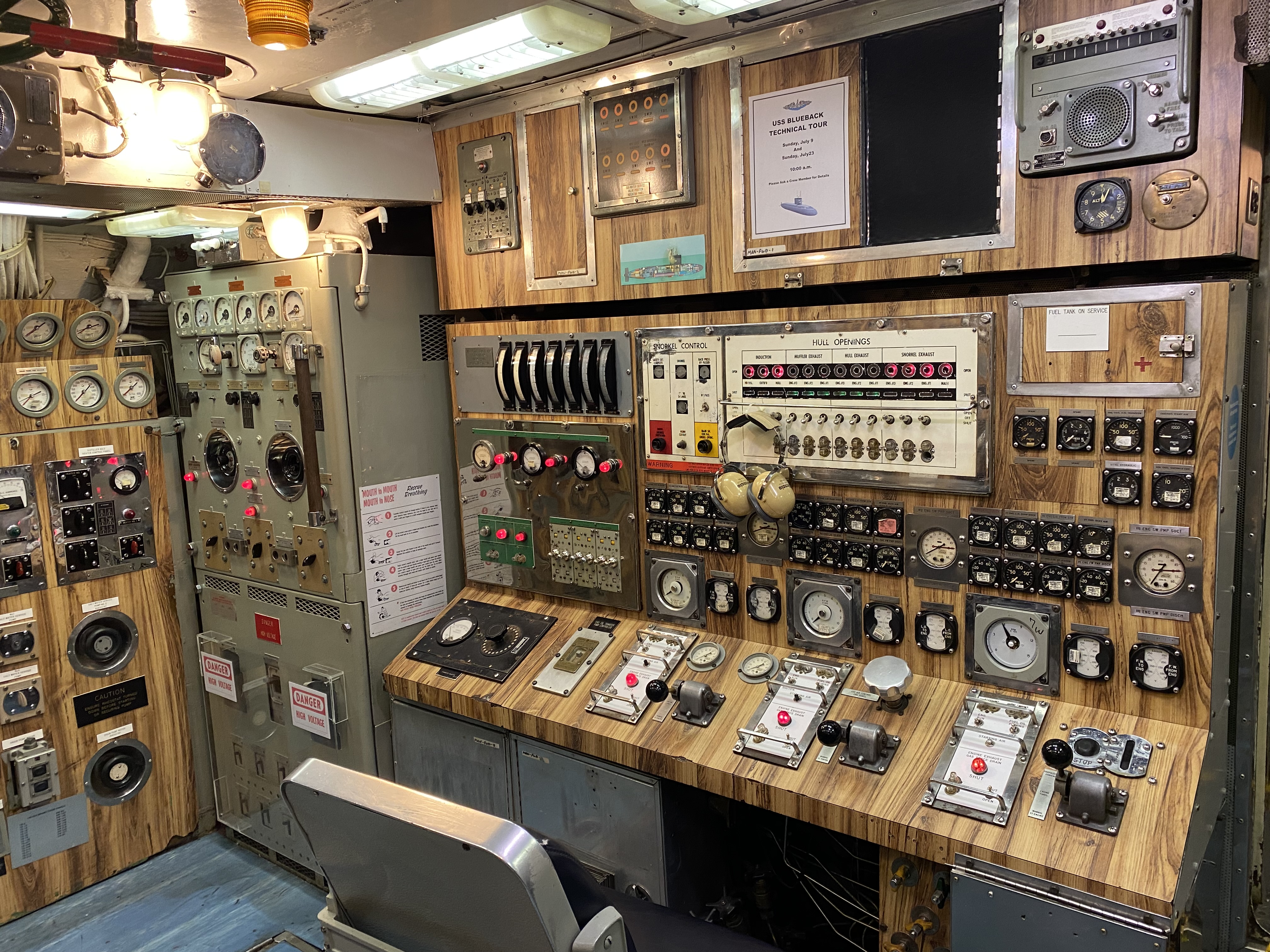
The diesel engines can be run in any configuration, but when surfaced normally two would be run, with the third being held in reserve. At snorkel depth, all three can be run (as noted above), but I’ve also been told two would generally be run. One would be charging the batteries and the other would provide power to the electric motor so the submarine would still be moving and not sitting still.
Normally, there would have been three men in the maneuvering room. These would be the engine console operator, the senior controller man, and the junior controller man. Their duties would be as follows:
- The Engine Console Operator (normally an Engineman) would man the engine control panel (the only remaining chair in the room). He has three identical sets of controls for the three engines. He would start the engines, get them up to the appropriate temperature, and shift control of the engines to the Junior Controller Man.
- The Junior Controller Man (a 3rd class Electrician’s Mate or above) would man the part of the propulsion control panel (with all the gauges measuring DC voltage) to control the batteries and generators. He would conduct battery charging while underway, and control the speed and load on the engines and generators.
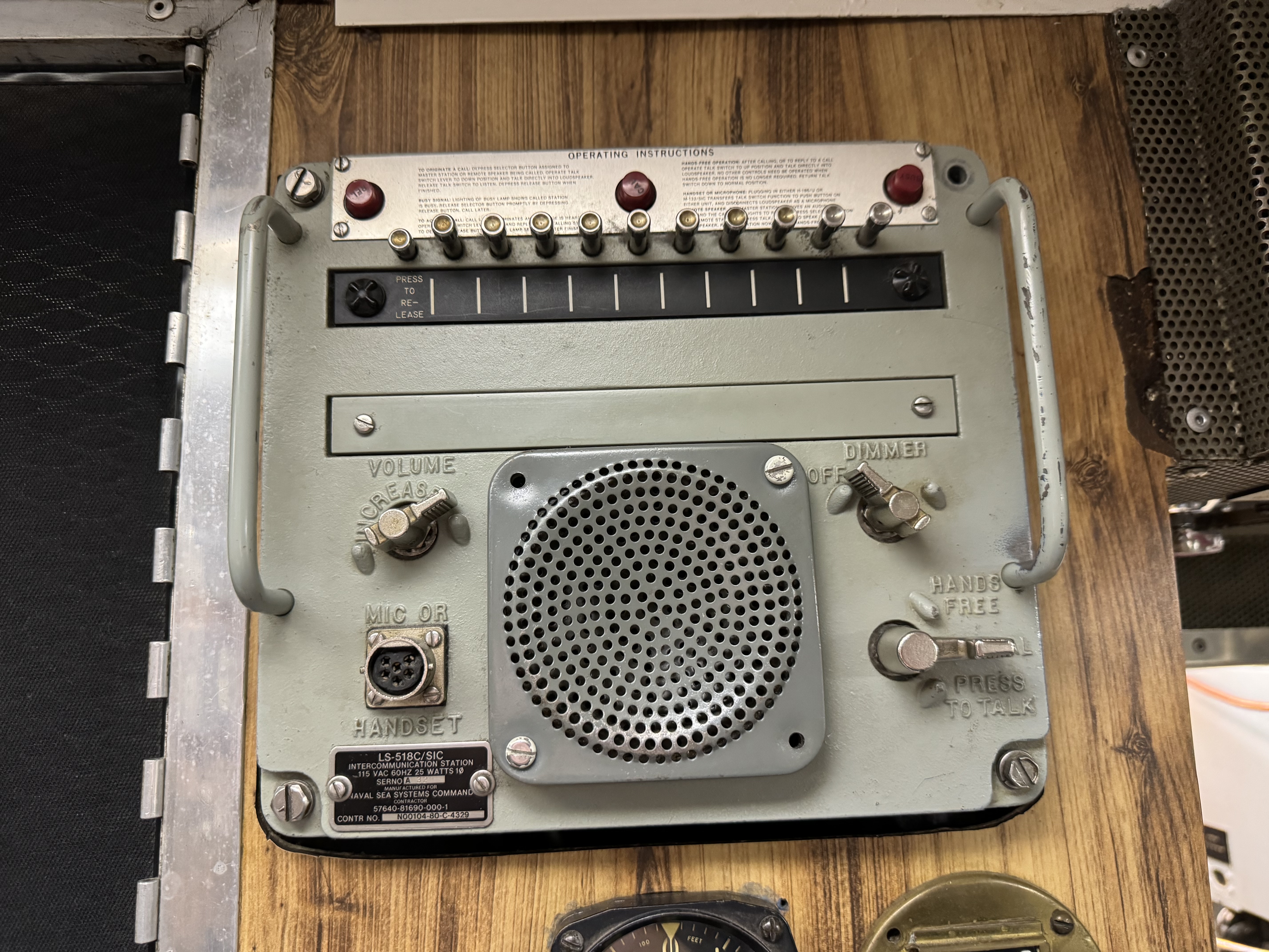
- The Senior Controller Man (also the Engineering Watch Supervisor) (normally an Electrician’s Mate) would man the chrome wheels to control the speed and direction of the submarine. He also oversaw the junior controller man. As the Engineering Watch Supervisor, he would be in charge of the engineering watchstanders, as well as man the X1J handset and 7MC microphone in this room to communicate with the control room.
There would also be additional watchstanders in the engineering spaces of the submarine. These would generally be as follows:
- The Throttleman (normally an Engineman) would be in the engine room coordinating the men in there, as well as running the freshwater stills.
- The Oiler (normally an Engineman) would run the fuel and lube oil purifiers. As the lowest in the engineering hierarchy, he would do the dirty jobs.
- The Auxiliary Electrician (normally an Electrician’s Mate) would be a roving watchstander/coffee runner who would check gravities on the batteries and address any electrical issues around the boat. This was a preferred watch to stand since you got to roam around the boat. Anyone standing the 0000 – 0600 watch would also get first dibs on any baked goods from the galley during this time.
- The Auxiliaryman of the Watch (normally a Machinist’s Mate) would be another roving watch to oversee the hydraulic plants, air conditioning, refrigeration, trim and drain pumps, and High-Pressure Air Compressors (HiPACs).
When in port, each duty section would have at least one qualified Junior Controller Man, Engine Console Operator, Throttleman, and Auxiliary Electrician. These four people would be required to conduct an in-port battery charge.
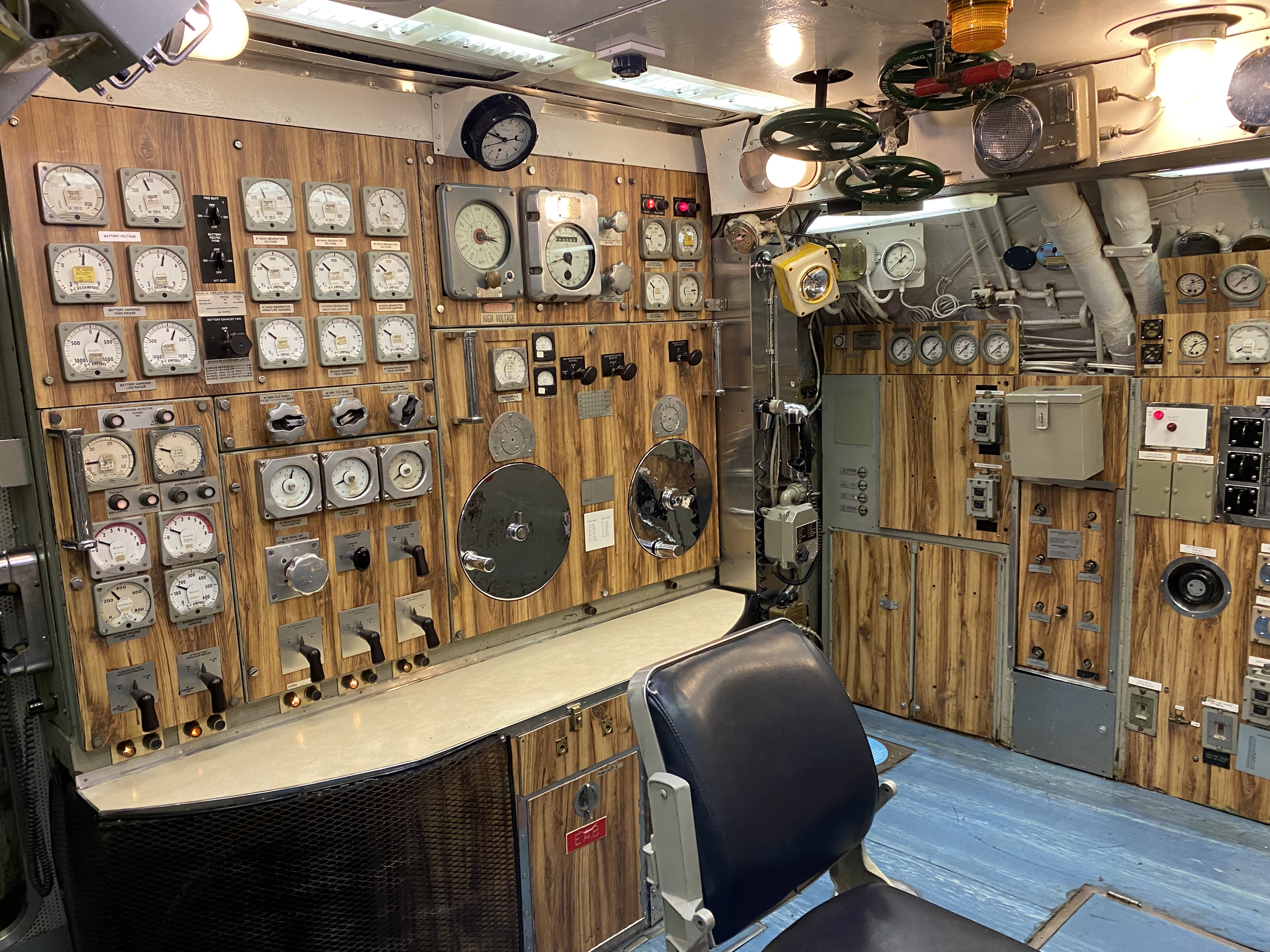
How is speed controlled?
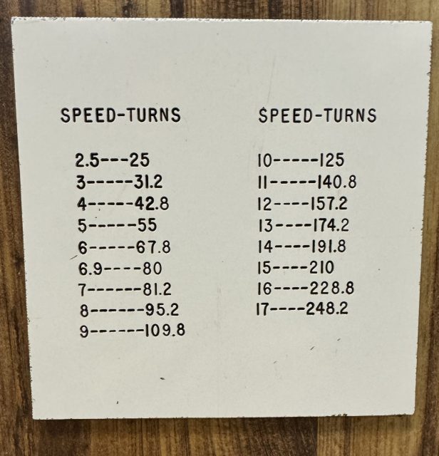
The large chrome wheels provide a rough control of the speed and direction of the propeller shaft. The left chrome wheel changes the speed by lining the batteries and electric motors up in series or parallel and increasing or decreasing the voltage. The small white placard in between the wheels shows how many turns (i.e. propeller RPMs) are required to attain certain speeds. Fine control of the speed is done with a smaller silver knurled knob above these wheels near the bottom of the propeller revolution indicator which increases or decreases the amount of field on the electric motors. The direction of the propeller shaft is actually controlled by the black knobs above the chrome wheels. The left one will change the direction of the shaft. The right one shifts control to manual mode, at which point the right chrome wheel will be used to change the polarity of the armatures in the electric motor causing the shaft to change direction.
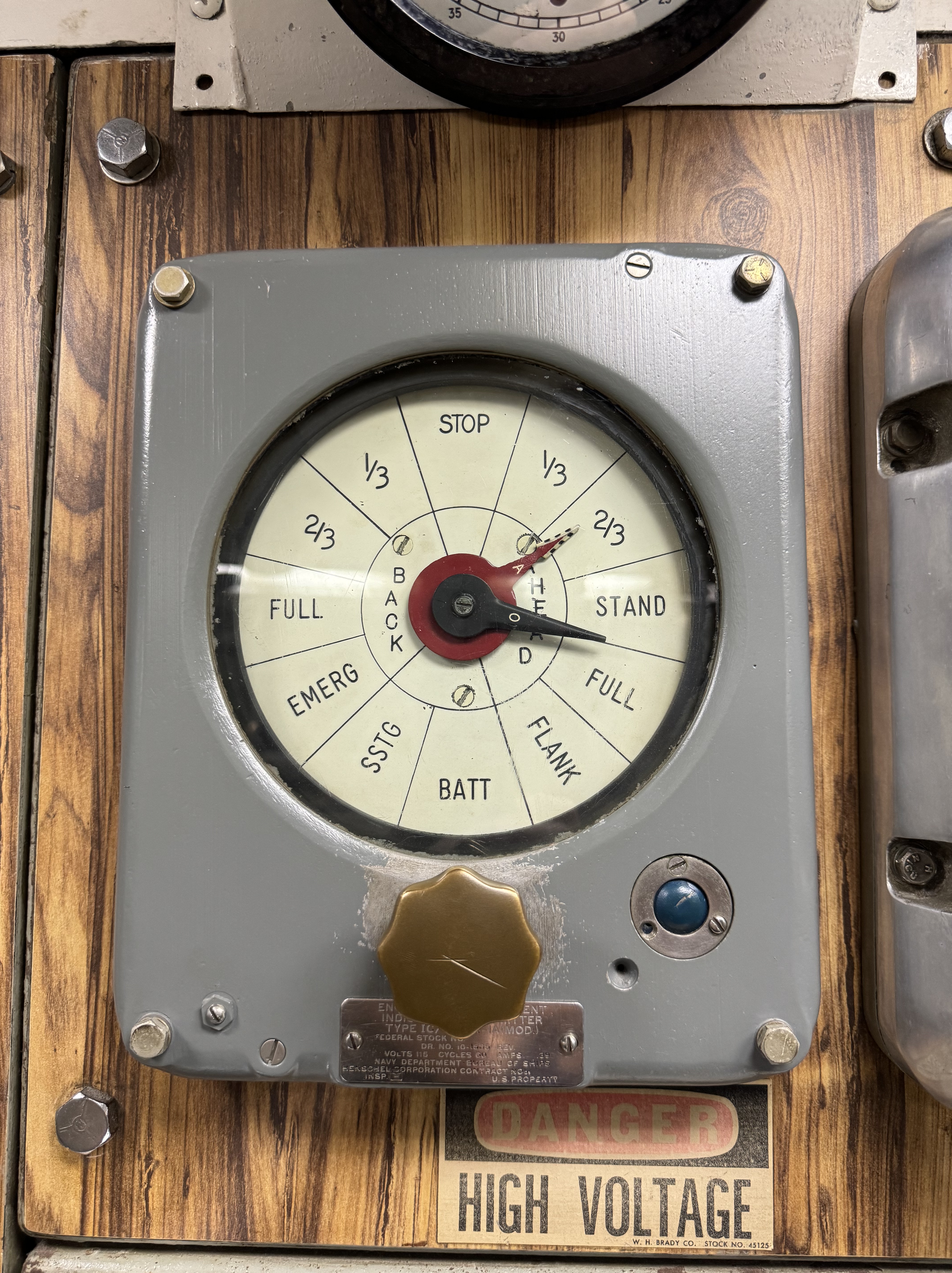
Much like older vessels, and modern nuclear-powered ones (subs and aircraft carriers) from what I’ve been told, there’s no direct control of the speed from the control room. Instead, the engine order telegraph (below the clock) would indicate the desired speed. There’s a set speed (and RPM) for each order on the engine order telegraph. If the sub’s flank speed is 21 knots, then each bell would be 4.2 knots.
There are two engine order telegraphs. One is up in the control room, operated by the helmsman, and one is down in the maneuvering room, operated by the throttle man.

Here’s how the process basically works:
- In the control room, the Officer of the Deck (OOD) orders a certain speed, such as ahead 1/3.
- The helmsman turns the knob on his engine order telegraph so the black pointer (labeled “O” for “order”) is on ahead 1/3.
- (An audible bell dings for every position the pointer moves. That is why they’re called “bells” and the helmsman “rings up an order.”)
- As this is happening up in the control room, the black pointer on the engine order telegraph in the maneuvering room simultaneously moves to the matching order.
- In the maneuvering room, the Senior Controller Man answers the order by turning the knob on his engine order telegraph to make the red arrow (labeled “A” for acknowledge/answer) to the same position.
- This is known as “answering bells.”
- The Senior Controller Man will turn the appropriate wheel in the appropriate direction to create the desired speed.
Aside from the engine order telegraph, communication of speed changes can also be done via a microphone circuit (such as the 7MC for maneuvering) over a “squawk box” or a sound-powered phone. For example, the OOD can order a specific speed, such as 4 knots, and will call the maneuvering room by saying, “Maneuvering, Conn, make turns for 4 knots.” The Engineering Officer of the Watch (EOOW) will then acknowledge by saying, “Make turns for 4 knots, Conn Maneuvering, Aye.” The specific speed on the shaft would be set as ordered.
Like other U.S. Navy diesel-electric submarines, Blueback‘s diesel engines use indirect drive. They are simply turning the three generators they’re connected to which produces electricity. The generators themselves are beneath and abaft the diesel engines.
When surfaced, the power from the generators charges the batteries but can be routed to the electric motor (AKA propulsion motor) in the Auxiliary Machinery Space (AMS) AKA shaft alley. The electric motor is what directly turns the propeller shaft. When submerged, the batteries power the electric motor. In other words, it’s not a direct-drive diesel powerplant (such as on WWII German U-boats). The entire submarine runs on electricity and is propelled by the electric motor. It’s also worth noting that submarines before the Tench-class had bulky reduction gears between their electric motors and propeller shafts. The purpose of these was to slow down the electric motor’s RPMs to a more appropriate speed for the propeller shafts. Diesel-electric submarines after that did not need reduction gears as the electric motors could operate at slow speeds.
The indirect drive system was chosen by the U.S. Navy for its flexibility. This also mitigated some of the issues of vibration at certain speeds because the diesel engines don’t directly drive the shaft and therefore don’t need to change speed. Since they’re connected to generators, they can be run at an optimal speed at all times. The downside of this system is that it’s heavier and more complex than direct drive systems.6
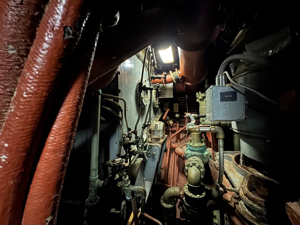
Auxiliary Machinery Space (AMS) AKA “Shaft Alley”
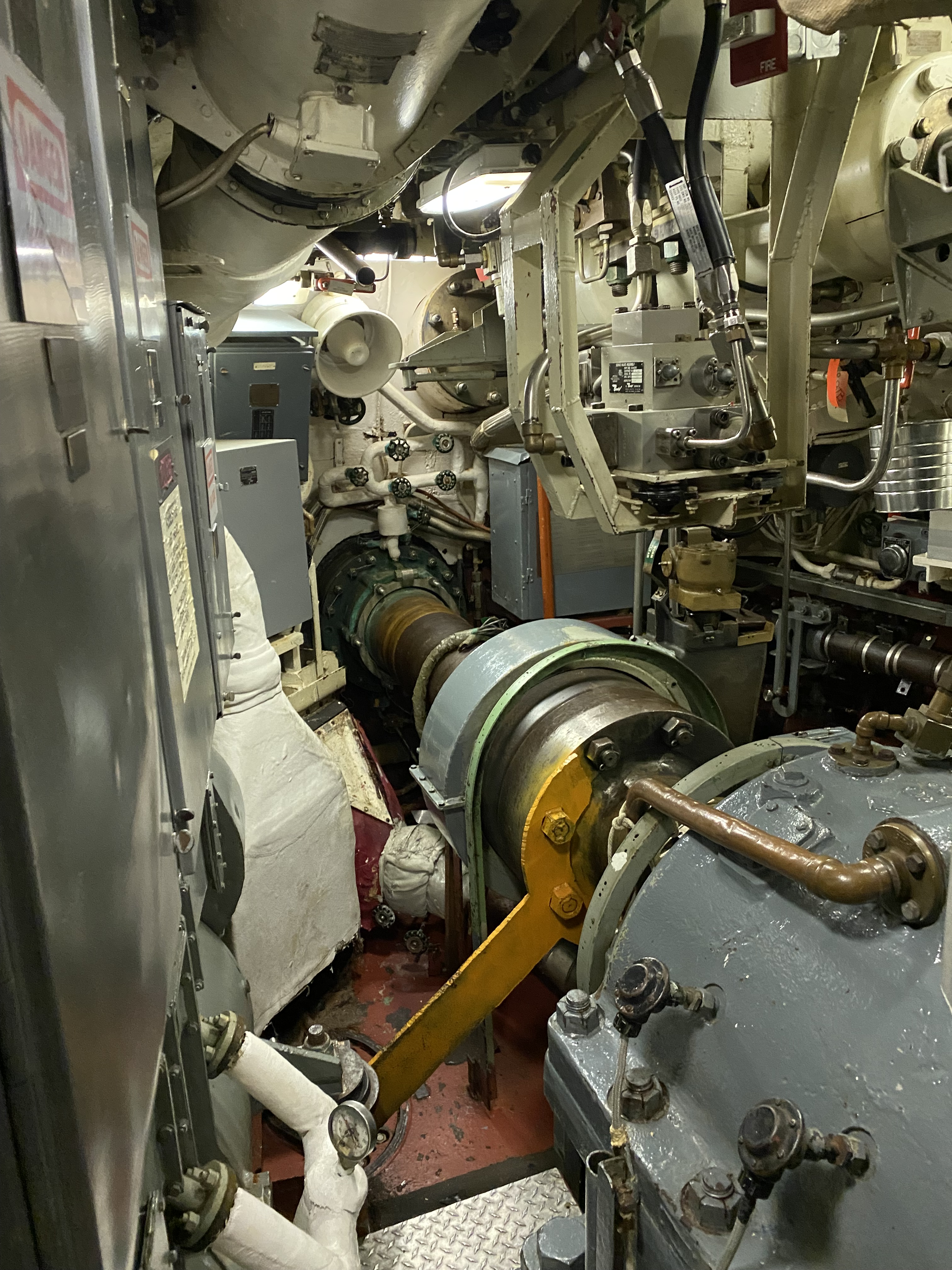
Many publications show Barbel-class submarines as having two electric motors. This is technically true, but they’re put end-to-end, creating two armatures, so it only appears as one. Together, they only drive one shaft. This electric motor is more powerful than the ones used on WWII fleet boats. Older fleet boats used less power when underwater and had dual electric motors (driving two shafts), but they only used half of each motor when submerged. The need for high-speed underwater endurance meant doubling the battery capacity and using the entire motor when submerged.7
The speed of the electric motor (and thus the screw AKA propeller) is dependent on voltage and amperage (i.e. current). A fleet boat’s propeller turns at 280 RPMs at 415 volts and 2,700 Amps. However, tests demonstrated that the electric motors could carry up to 3,000 amps continuously. Further testing showed that higher voltages could be handled if all batteries were in series. At a 1/2 hour rate of discharge, a total of 6,500 shp (or more) could be attained compared to 4,700 shp at the 1-hour discharge rate.8 Compare this to Blueback‘s motor which turns a larger single screw at 212 RPM and generates a total of 6,440 shp at 880 volts and 5,950 Amps total.
Blueback‘s electric motor is designed to operate its two armatures with a total power consumption rate of up to 5,400 amps with the batteries in series for up to four hours. The motor can vary the speed of the propeller from about 25 – 230 RPMs. The motor itself is enclosed in an air cooler which is cooled with seawater. The lubricating oil is also cooled with seawater.
The propeller shaft is 29 feet 10 inches long and 12.5 inches in diameter. It is designed to turn at 230 RPM at 7,780 shp and 162 RPM at 3,150 shp for continuous duty. The axial load of the shaft itself acts upon a Kingsbury thrust bearing. Essentially, this thrust bearing is what the screw and shaft are pushing against and moving the submarine forward. Without it, the screw would literally push the shaft right through the electric motor.
Conclusion
Ultimately, the Fairbanks Morse 38D8-1/8 diesel engine has a storied history within the United States, being applied to marine, railway, and land-based roles. While the design has remained largely unchanged for over 85 years, efforts have been made to improve the engine’s fuel efficiency. Renowned for their durability and reliability, the robust design of the 38D8-1/8 remains in continuous production to this day, and will likely continue for the foreseeable future.
Notes
- “FM 38D 8-1/8 Diesel & Dual Fuel,” Fairbanks Morse Defense, 2023, https://www.fairbanksmorsedefense.com/solutions/engines/fm-38d-8-18. Hereafter referred to as “FMDefense.” ↩︎
- kiloWatt brake (kWb), 1 bhp = 745.7 Watts (0.7457 kWb), therefore 1 kWb = 1.34 bhp ↩︎
- FMDefense ↩︎
- Martin Leduc, “The Fairbanks Morse 38D8⅛,” Dieselduck.info, August 2000, https://www.dieselduck.info/machine/01%20prime%20movers/fairbanks_morse/fairbanks_morse.htm. ↩︎
- “Paxman History – A Glossary of Diesel Terms,” paxmanhistory.org.uk, February 11, 2015, https://www.paxmanhistory.org.uk/glossary.htm. ↩︎
- Norman Friedman, U.S. Submarines since 1945, Revised Edition: An Illustrated Design History (Annapolis, MD: Naval Institute Press, 2018), 34. ↩︎
- Friedman, 33 – 34. ↩︎
- Friedman, 275. ↩︎
Bibliography
Leduc, Martin. “The Fairbanks Morse 38D8⅛.” Dieselduck.info. August 2000. https://www.dieselduck.info/machine/01%20prime%20movers/fairbanks_morse/fairbanks_morse.htm.
“FM 38D 8-1/8 Diesel & Dual Fuel.” Fairbanks Morse Defense. 2023. https://www.fairbanksmorsedefense.com/solutions/engines/fm-38d-8-18.
Friedman, Norman. U.S. Submarines since 1945, Revised Edition: An Illustrated Design History. Annapolis, MD: Naval Institute Press, 2018.
Weinstein, Joshua. “Fairbanks-Morse 38 8-1/8: The Immortal Diesel.” Junkyardmob.com. June 8, 2022. https://www.junkyardmob.com/guides/fairbanks-morse-diesel-engine.
“Paxman History – A Glossary of Diesel Terms.” paxmanhistory.org.uk. February 11, 2015. https://www.paxmanhistory.org.uk/glossary.htm.

Outstanding post, Tim! Fascinating that they got the design right so log ago and that these engines are still in service.
LikeLike