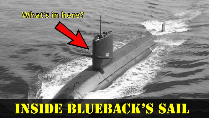
Have you ever looked at a modern submarine and wondered what that square structure sticking out of the dorsal side is? Simply put, it’s known as a sail or a fairwater in American parlance, or a fin in British English.
Obviously, a submarine has no interest in wind power, but navies like to use old terms for things…because of traditions.1 The simple purpose of the sail is to house the masts of a submarine. These can be periscopes, radars, communications, ESM/ECM antennas, and even a snorkel. These masts would retract down into the sail (in some cases into the hull, as well) and be flush with the top of the sail to present a hydrodynamically efficient structure.
Here, we’ll examine the development of submarine sails from the conning tower of WWII fleet boats to the sails of modern submarines.
The First Sail
The first designs for submarines go all the way back to the 1500s, with Leonardo da Vinci sketching out a submersible design around 1515. Other designs would come, but a century later, Cornelius Drebbel’s vessel in 1620 was likely the first navigable submersible. Arguably, the first submarine with an actual sail was built from 1799-1800. American engineer, Robert Fulton, was working in France and built the 21-foot 4-inch long Nautilus. This submarine had a copper-sheathed hull, a mast with two sails for surface propulsion, along with two hand-cranked screws for underwater propulsion. The mast was unstepped before diving the submarine. The depth of the submarine was measured with a barometer, and breathable air for the four-man crew was supplied from compressed air flasks.2 It’s not known how fast Nautilus could travel under sail.
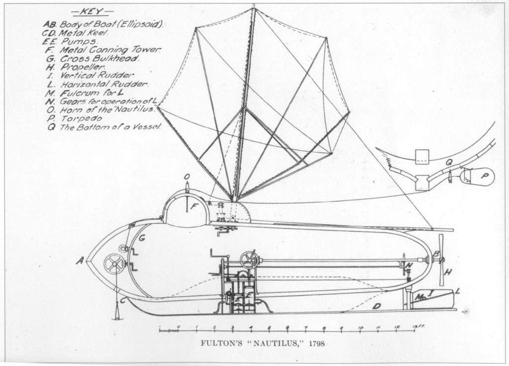
Fulton’s Nautilus was tested on the River Seine in Paris. In July 1801, further tests were conducted in the port of Brest, where the boat descended to depths of nearly 30 feet and remained submerged for over an hour. Using the “horn” (i.e., an auger), Nautilus could attach a “torpedo” (an explosive charge) to the bottom of a vessel and then move away before it was detonated. This capability was demonstrated when it blew up a 40-foot sloop.3
Sailing a Submarine Home
The use of actual sails on a submarine didn’t end with Fulton’s Nautilus. In fact, they would make a comeback in May of 1921 when the submarine USS R-14 was participating in a search-and-rescue mission for the ocean-going tug, USS Conestoga, which had disappeared on its way to the South Pacific.4
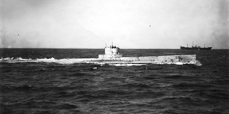
Operating on the surface about 140 nautical miles away from Pearl Harbor, R-14 ran out of fuel due to seawater contamination and lost all radio communications. Unable to call for help, with only enough food to last for five days, and with the distance too great to cover on battery power alone, the submarine was dead in the water and adrift. However, the engineering officer, Roy Trent Gallemore, came up with the plan to propel the submarine using sails.6
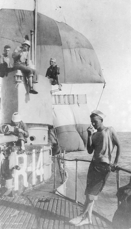
Fashioning a yard out of pipe rack frames and using the torpedo loading crane as a mast, the crew made a foresail out of eight hammocks. It worked and allowed the sub to make just over 1 knot and regain rudder control. The crew set a course back to Pearl Harbor.8
A mainsail made from six blankets was fashioned and attached to the radio mast. This increased their speed by an additional 0.5 knots. Finally, a mizzen made from eight blankets, also attached to bed frames, was rigged on the aft end of the conning tower and added another 0.5 knots of speed. With a top speed of about 2 knots, R-14 was underway on wind power. Eventually, the windmilling effect of the screws turning in the water allowed the generators to begin (very slowly) charging the batteries, and the submarine arrived in Hilo, Hawaii, while on battery propulsion, some 64 hours later. R-14’s captain, Lieutenant Alexander Dean Douglas, received a commendation for his crew’s clever problem solving from future Admiral (then Commander) Chester W. Nimitz, his Submarine Division Commander.9
Conning Towers
To conn a vessel simply means to direct its movements. Whichever officer is conning a vessel is said to “have the conn.” A ship is primarily conned from the bridge (which may be part of the conning tower), but with submarines, the bridge may not be accessible due to being submerged, so the control room serves as the conn.
Regarding conning towers on submarines, naval historian Norman Friedman specifically defines the conning tower of a submarine as a smaller pressure hull that’s attached to the main pressure hull and surrounded by the non-watertight fairwater superstructure (which is often erroneously referred to as a conning tower).11 Conning towers were originally vertical cylinders, and the use of horizontal cylinders for conning towers didn’t appear on U.S. submarines until the construction of USS Argonaut (V-4/SM-1/SS-166). They became standard after that.12
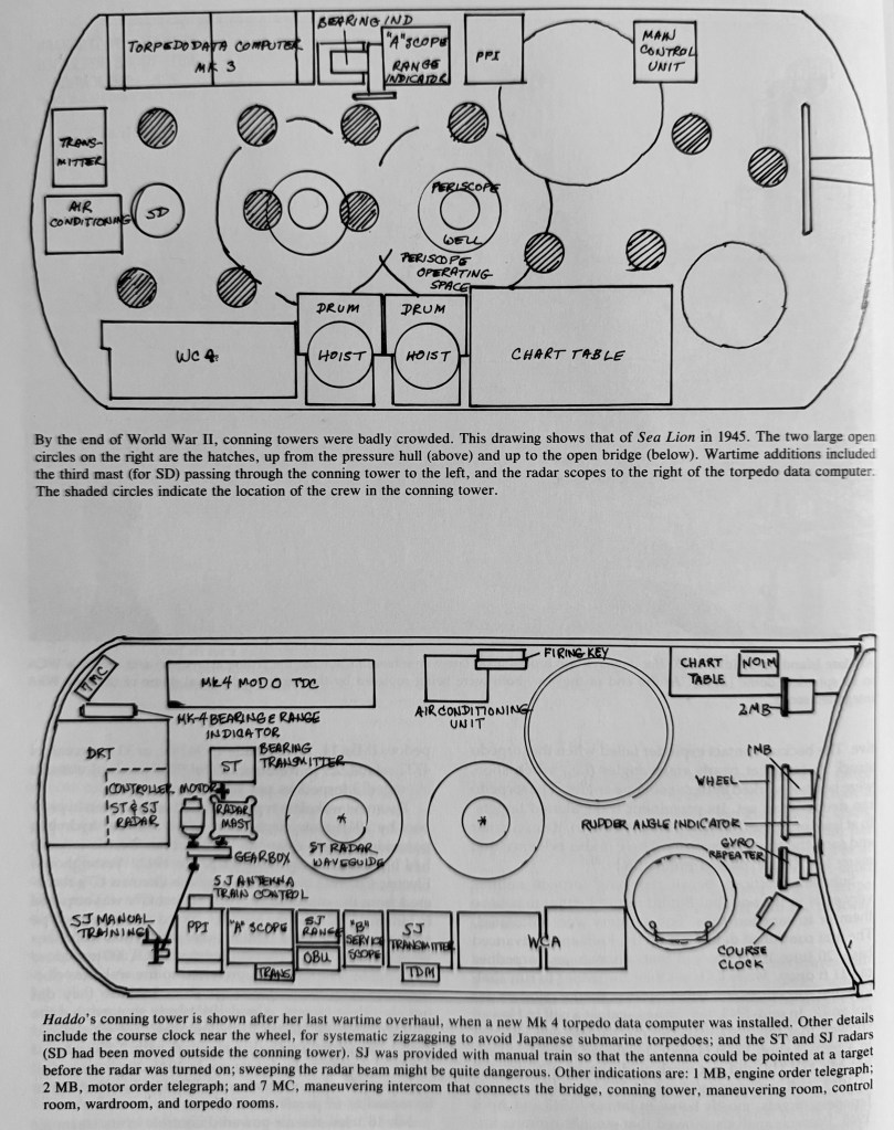
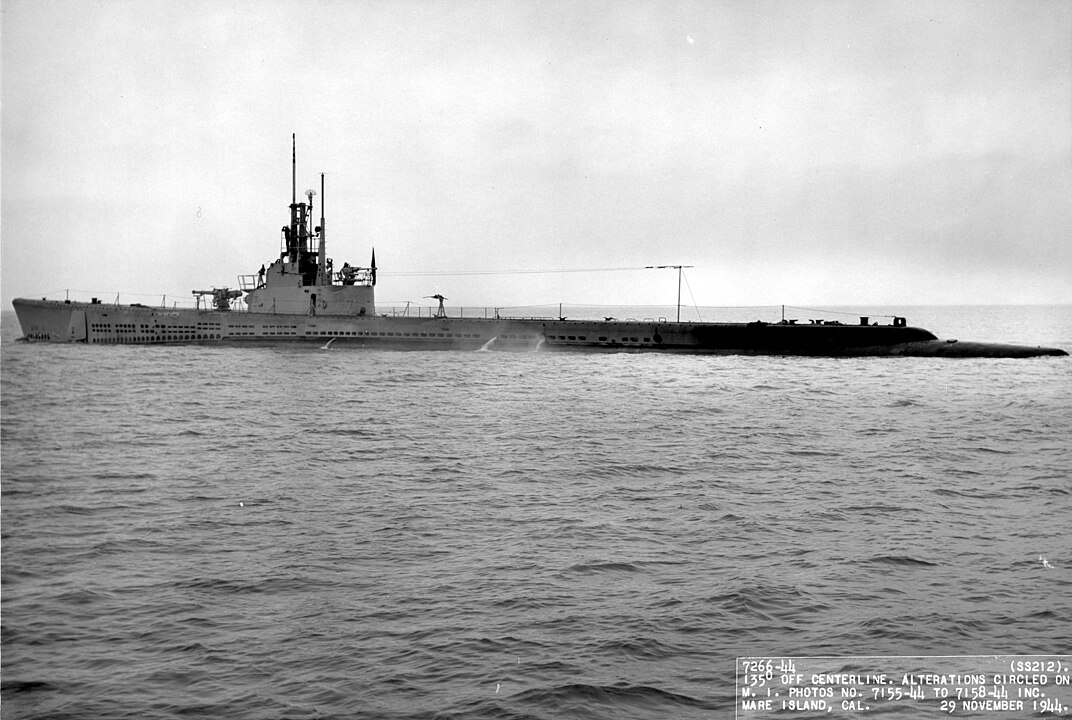
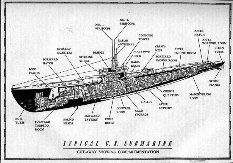
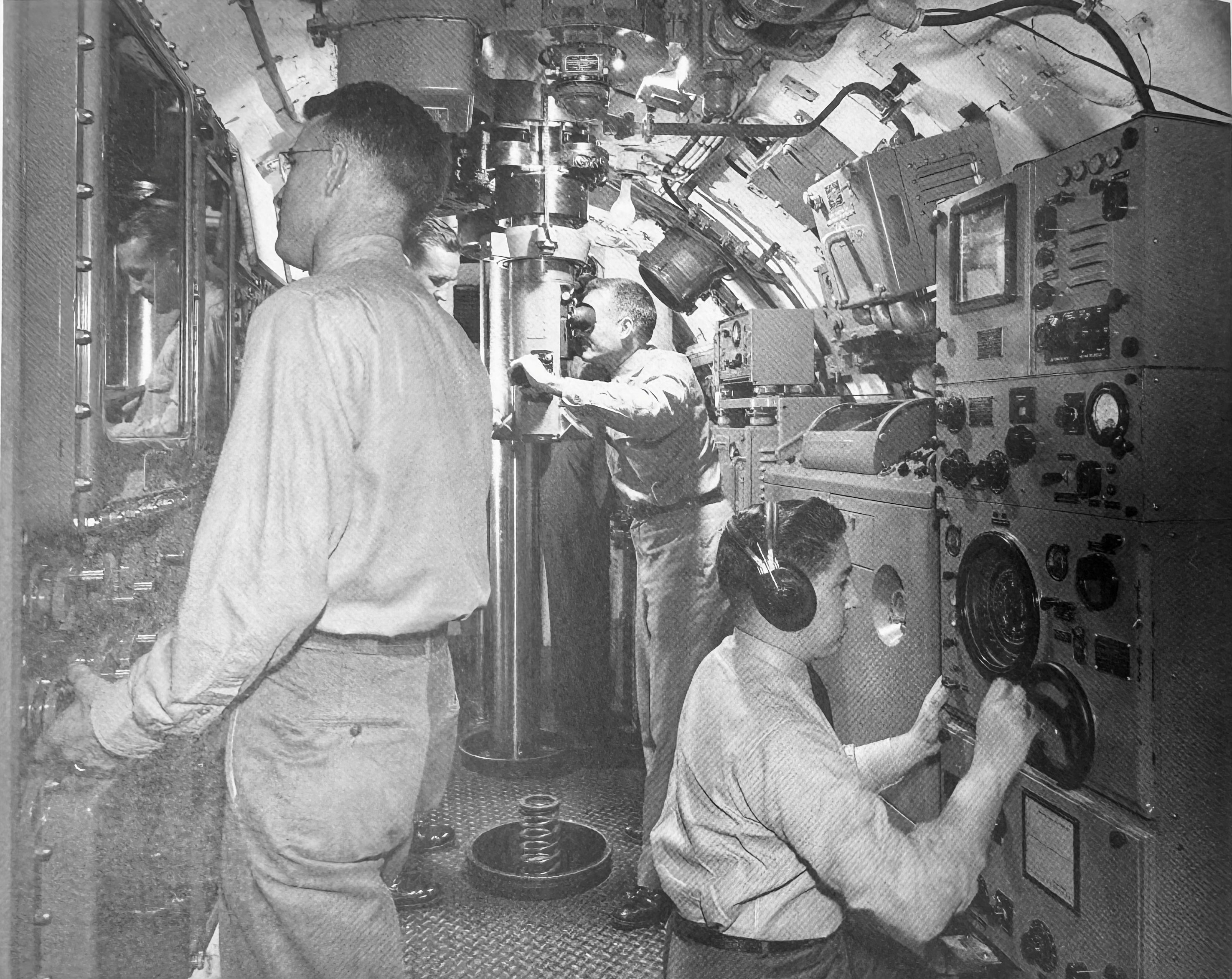
On older submarines (like WWII-era fleet boats), the superstructure, AKA fairwater, served to house the conning tower, bridge, lookout stations, masts, periscopes, and AA gun platforms. Since these boats were designed to run primarily on the surface of the water, only submerging when attacking or for concealment, the primary station to conn the submarine was from the bridge at the forward end of the fairwater. Lookouts would be stationed on the periscope shears to scan the surroundings, and the AA guns would be manned on the platforms, as well. The conning tower inside the superstructure of WWII fleet boats was used for attack, steering via the main helm, and served as the captain’s battle station. The periscopes, helm, radar consoles, and fire control equipment would be in the conning tower, as well. This is that small, cramped space where the captain is looking through the periscopes and directing an attack on an enemy ship that you see in WWII movies on U.S. submarines.
The sail is often confused with a conning tower. However, they’re not the same thing. The term “sail” began to be used on submarines following World War II.
Transition to the Modern Sail
Note: Different authors have different definitions when referring to what constitutes a sail and what doesn’t. By Norman Friedman’s above definition, a conning tower specifically refers to the separate pressure hull above the main hull. In contrast, Stefan Terzibaschitsch uses the terms somewhat interchangeably. He frequently uses the term conning tower even when the superstructure doesn’t actually contain a separate pressure hull, but notes that the term “sail” would eventually be used. In modern U.S. submarines, the term sail is almost exclusively used, and the term conning tower is seldom used unless in reference to an older fleet boat. These definitions are further reinforced by the pedantic nature of many sailors and naval terminology. For this post, the author is using Friedman’s definition of the conning tower being a pressure hull inside the superstructure/fairwater.
The transition from submarines having conning towers to sails was gradual, and there’s no definitive date as to when the term sail came to be applied to a submarine’s superstructure. However, the following will attempt to trace some of those changes.
GUPPY Conning Towers/Sails
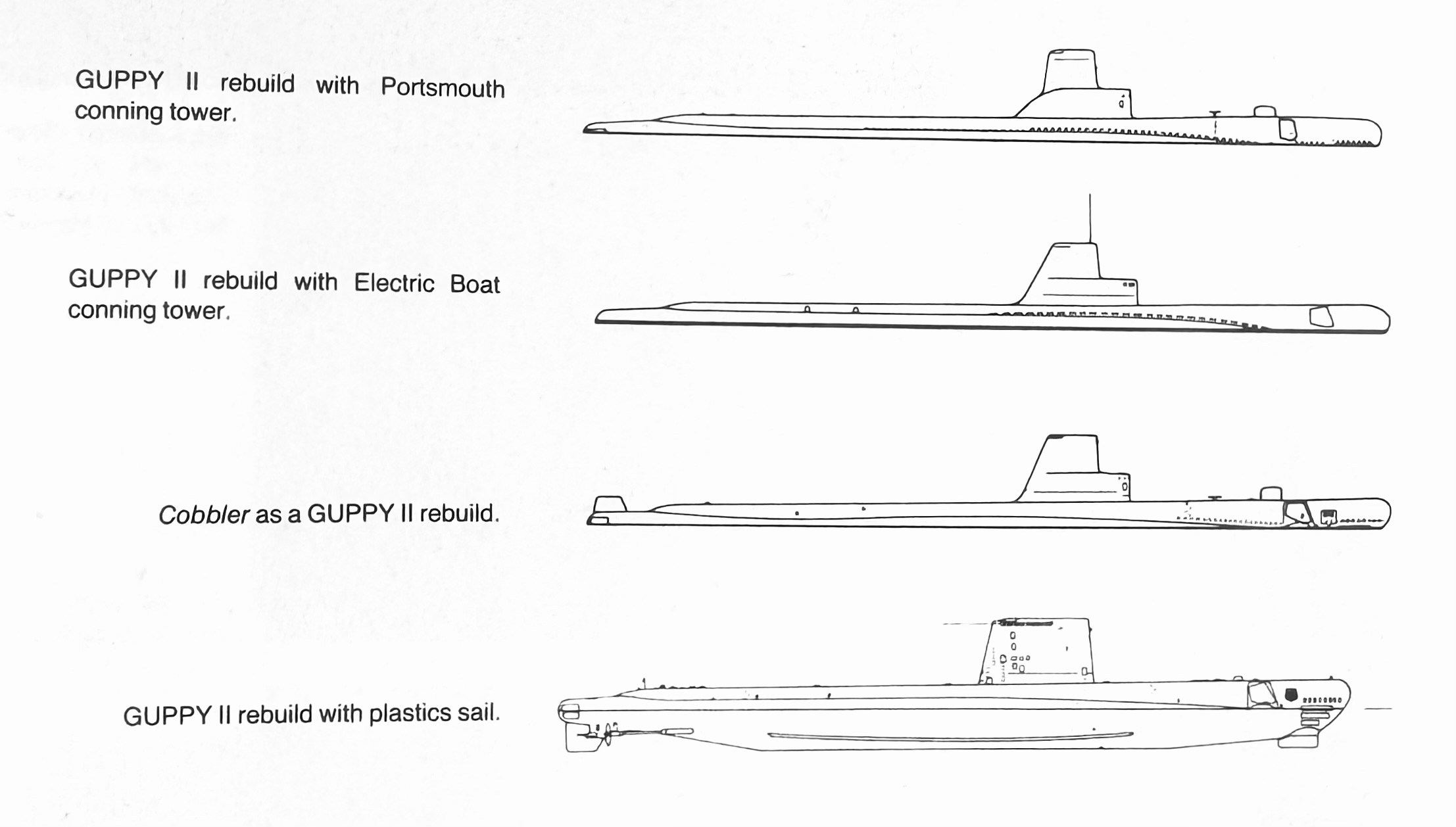
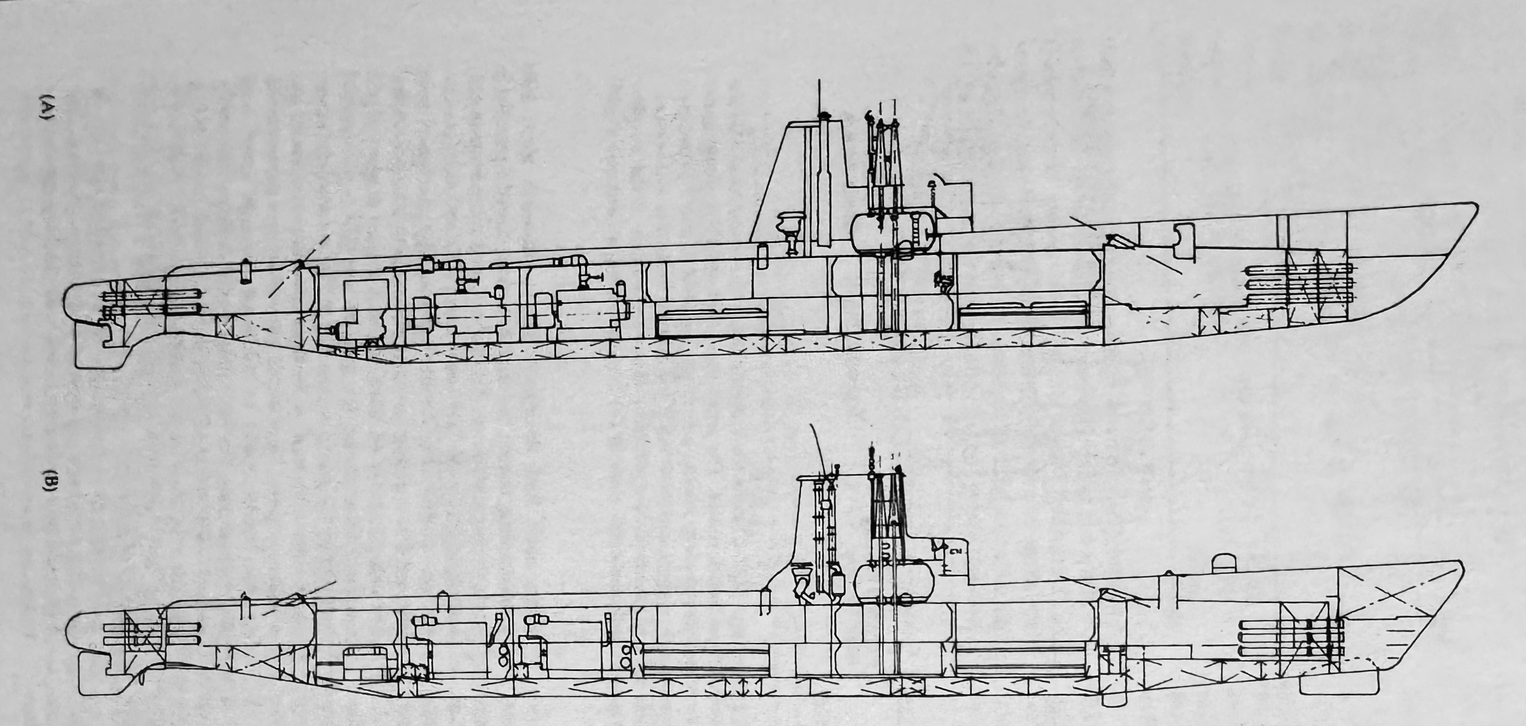
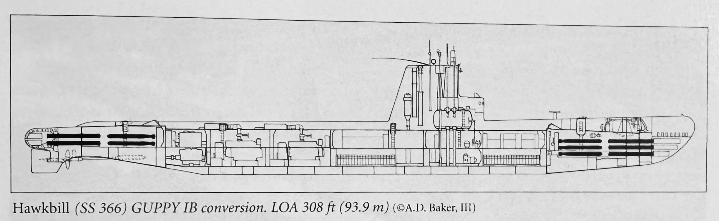
Following WWII, there was a bevy of different submarine designs throughout the 1950s, including updating the existing WWII Fleet Boats via the GUPPY conversions.16 The GUPPY II program, conducted by the Electric Boat Company and Portsmouth Naval Shipyard, added some changes to the design of the fairwater on the older fleet boats. Initially, there were differences between the two shipyards in the design of the fairwater, but these disappeared as the program progressed.17 All nine boats that were converted during the GUPPY III program were fitted with higher fiberglass superstructures.18
The Attack Center
The growing amount of electronics and advancements in submarine fire control resulted in increasingly large systems that could no longer fit inside a fleet boat’s conning tower. The answer was to completely remove the conning tower and move all fire control instruments down into the submarine’s control room.
By 1945, submarines had gained so many electronics that there was a need to integrate all of these systems into a single space. Since Combat Information Centers (CICs) were already a feature on surface ships, submarines with CICs would have the Torpedo Data Computer (TDC), Dead Reckoning Tracker (DRT), communications, fire control, radio, and Electronic Countermeasures (ECM). USS Corsair (SS-435), commissioned on 8 November 1946, featured a conning tower that was five feet longer to accommodate a separate Combat Information Center (CIC). A critique of submarine design in September 1945 requested that the CIC be moved down into the pressure hull next to the control room. In addition to reducing the size of the conning tower, it would reduce the size of the fairwater, and thus, the submarine’s surface silhouette. Modern submarines feature attack centers next to the control room.24
The term attack center was coined at the Submarine Officers Conference in December 1946. Postwar developments in fire control introduced the Mark 101 fire control system, which was too large to fit into an existing submarine’s conning tower since it included more than just the TDC. All submarines with the Mark 101 featured an attack center on one side of the control room. While this crowded the control room, a proposal from Submarine Development Group 2 (SubDevGru2) in January 1951 had the sonar consoles moved to a separate space. Additionally, as sonar replaced the periscopes as the main sensor for submarines, the logic of having a conning tower, with the TDC next to the periscopes, was no longer applicable. Since high underwater speed was needed in submarines, the conning tower (and large fairwater) needed to be eliminated, but it came at the price of having the periscopes lower inside the pressure hull, and thus, the submarine rode nearer to the surface at periscope depth and at greater risk of broaching the surface. However, one upshot is that it centralized all of the submarine’s controls into the control room and allowed the skipper to have immediate access to any evolving tactical situation as displayed on the attack center.25
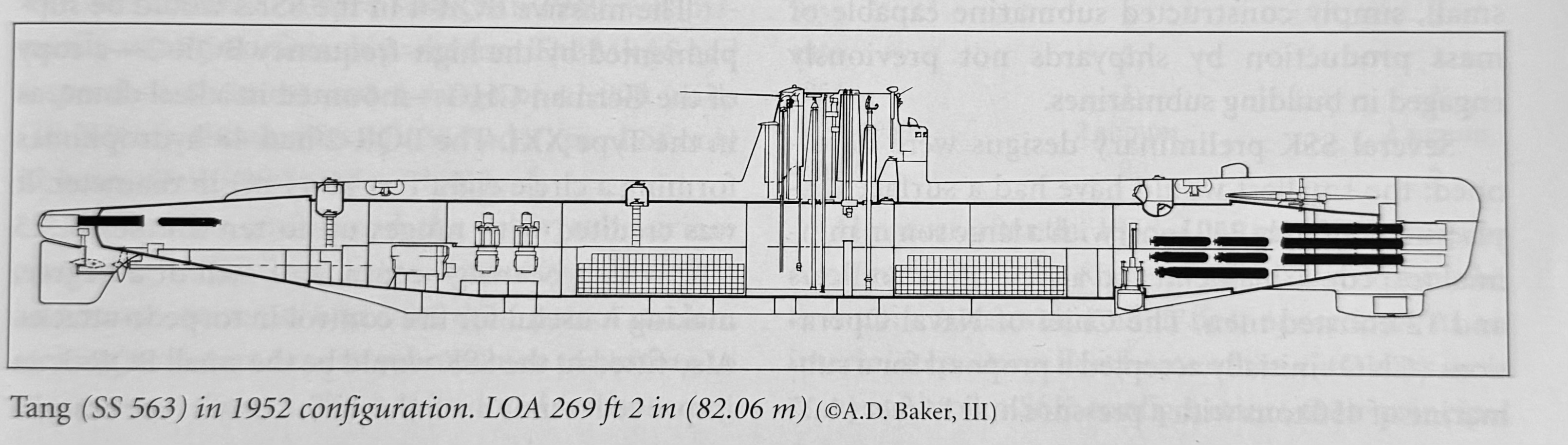
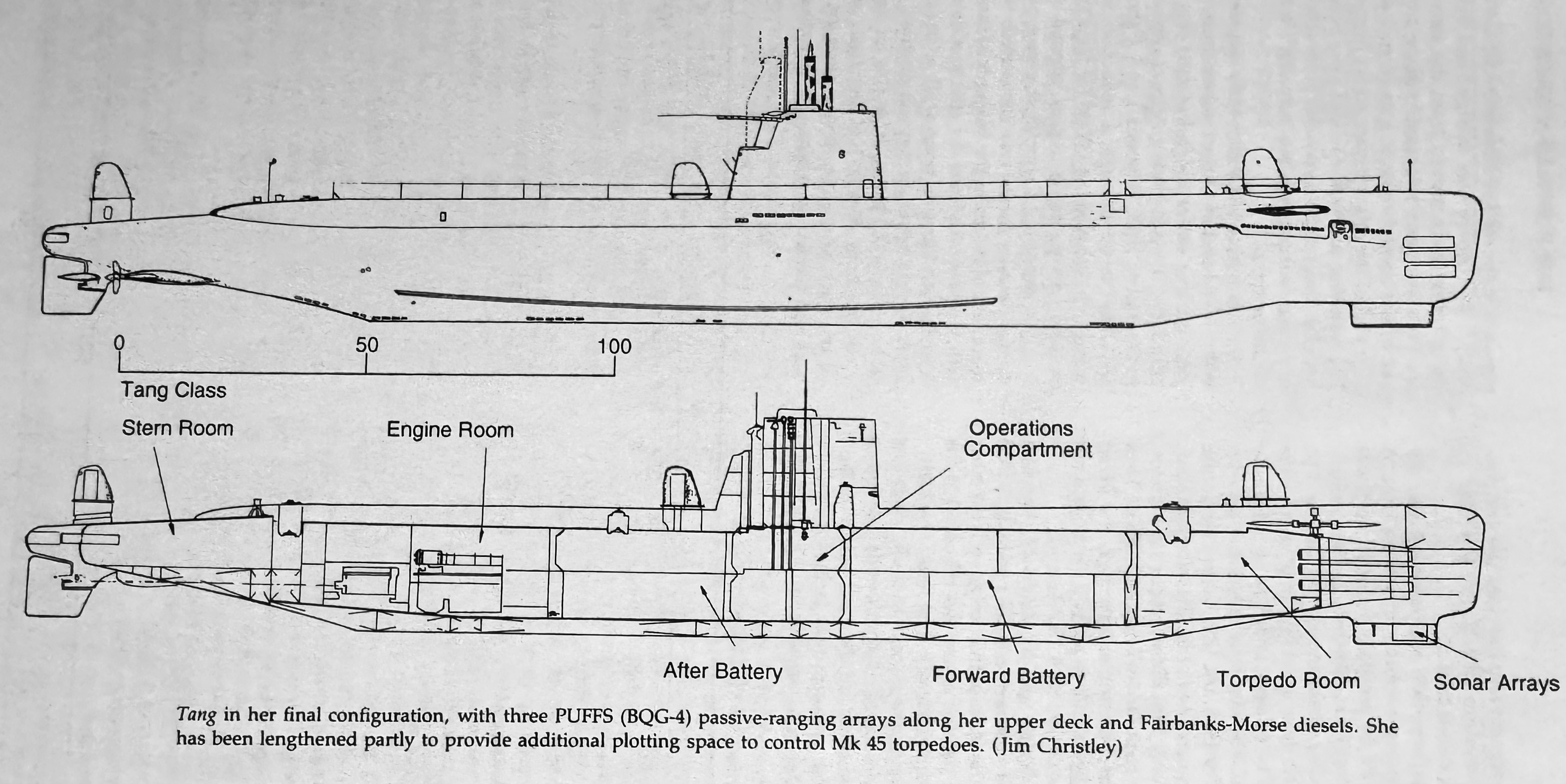
Tang-class
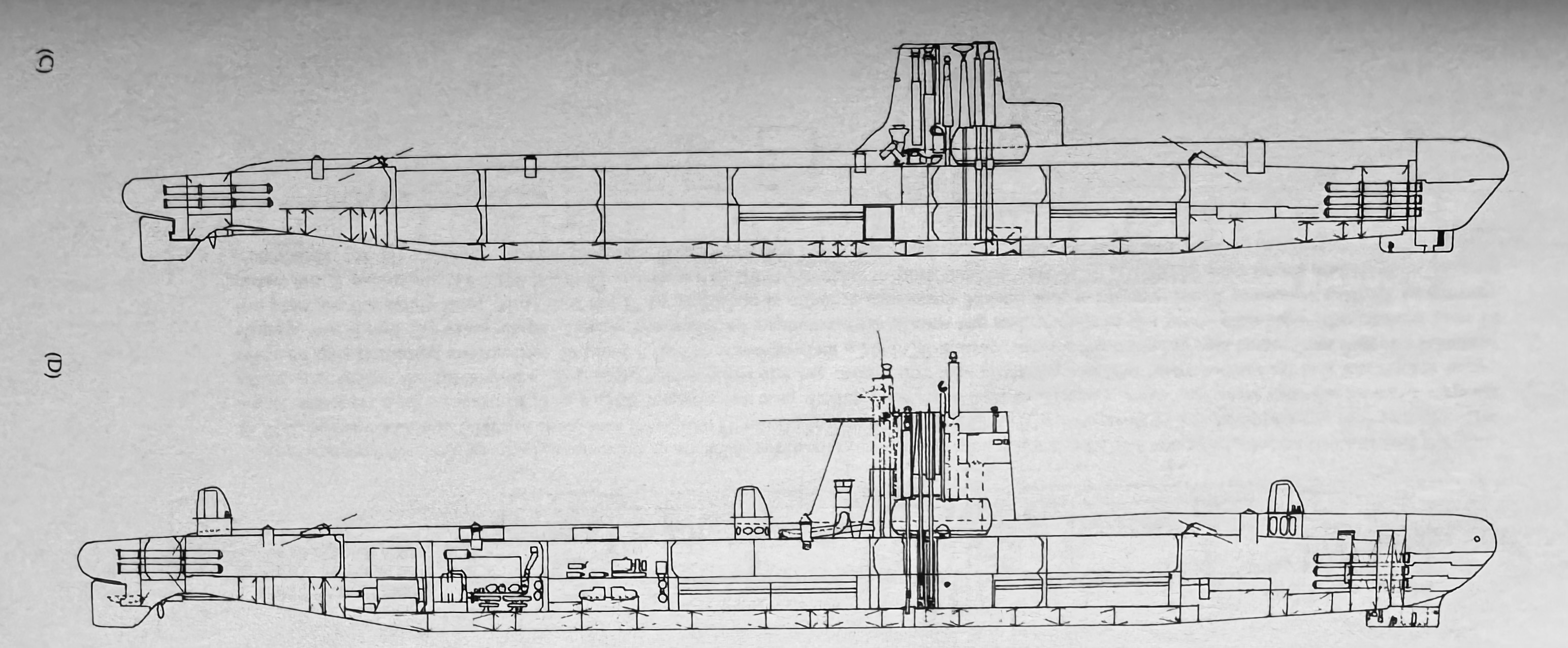
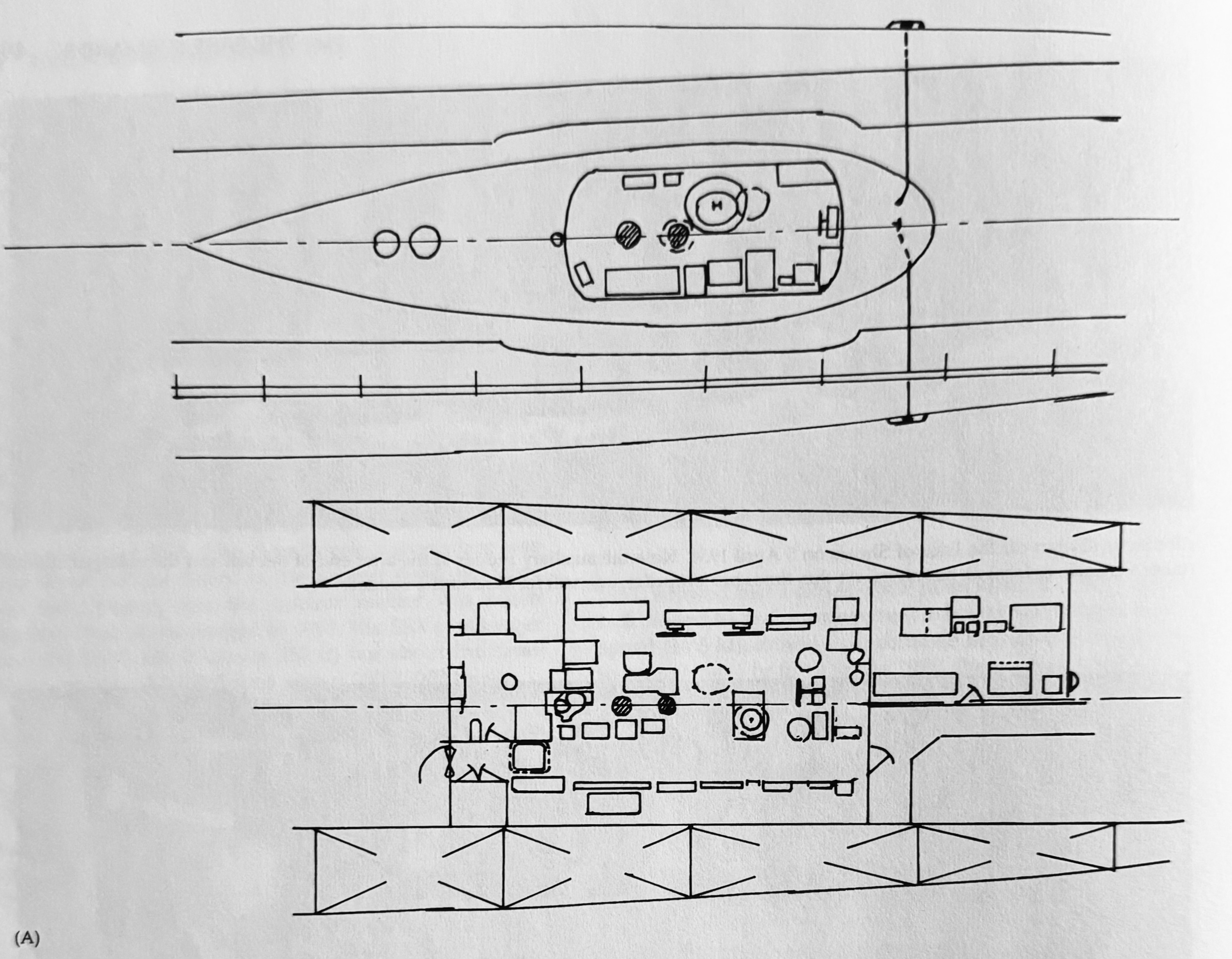
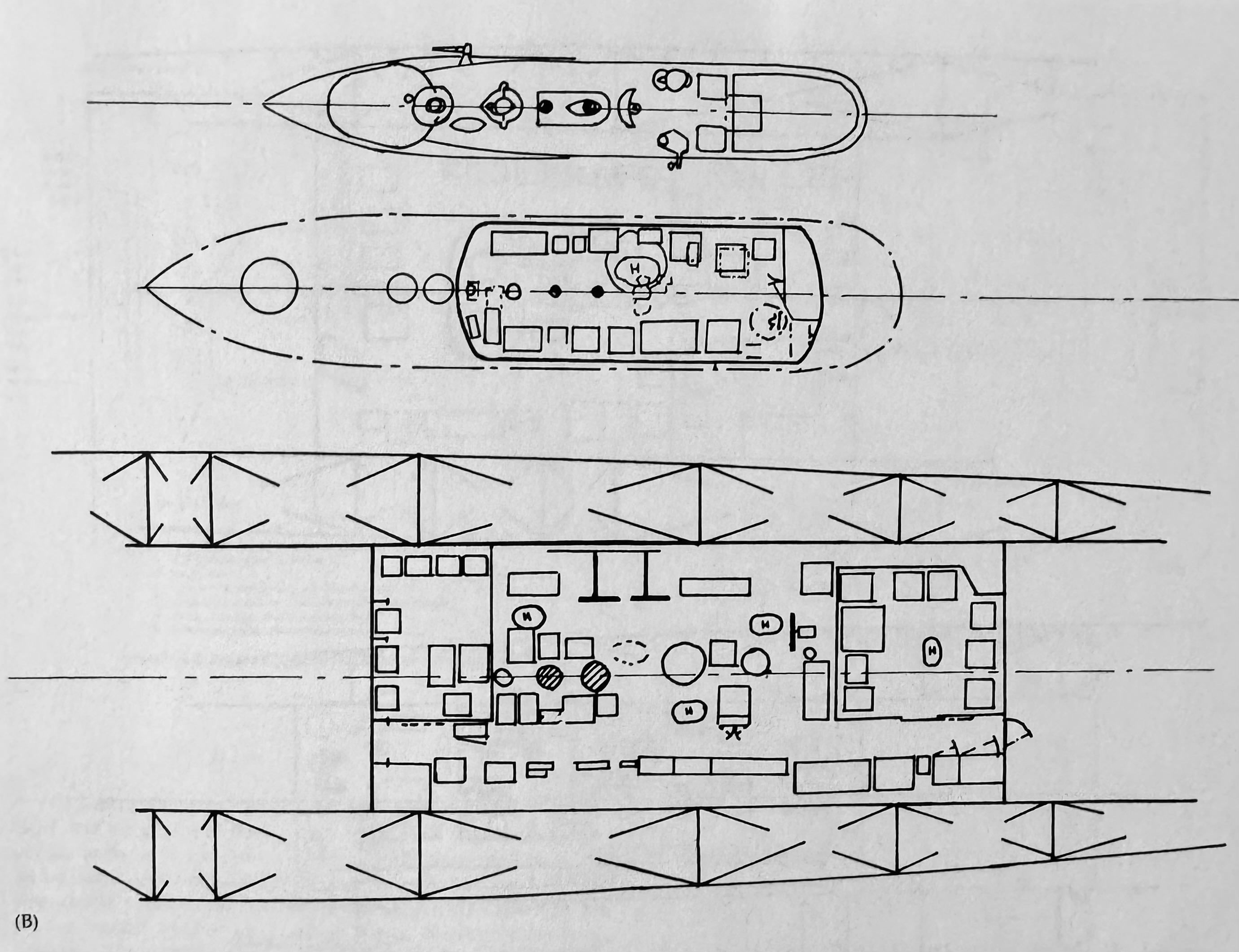
As postwar submarine designs advanced, studies were conducted to improve the underwater performance of submarines. The Tang-class boats were the first purpose-built submarines to incorporate many of these features and were designed for greater underwater performance than surfaced performance. Model tests in January 1947 showed that the bridge structure of a submarine created some 51% of the total underwater resistance at 15 knots, with all appendages (minus the essentials such as rudder, shafts, struts, and bilge keels) contributing 60%. To improve streamlining of the boat, the conning tower was eliminated, and the fire control systems were moved down into the control room to create an attack center. While this did create a crowded control room, the problem was alleviated with the introduction of the control room layout of the Barbel-class.26
The streamlined sail structure was introduced on the Tang-class boat, USS Trigger (SS-564), which served as a testbed for the “plastics sail,” which was used extensively in the later fleet boat modernizations. Although when originally commissioned (on 31 March 1952), Trigger had a more conventional appearing superstructure.27
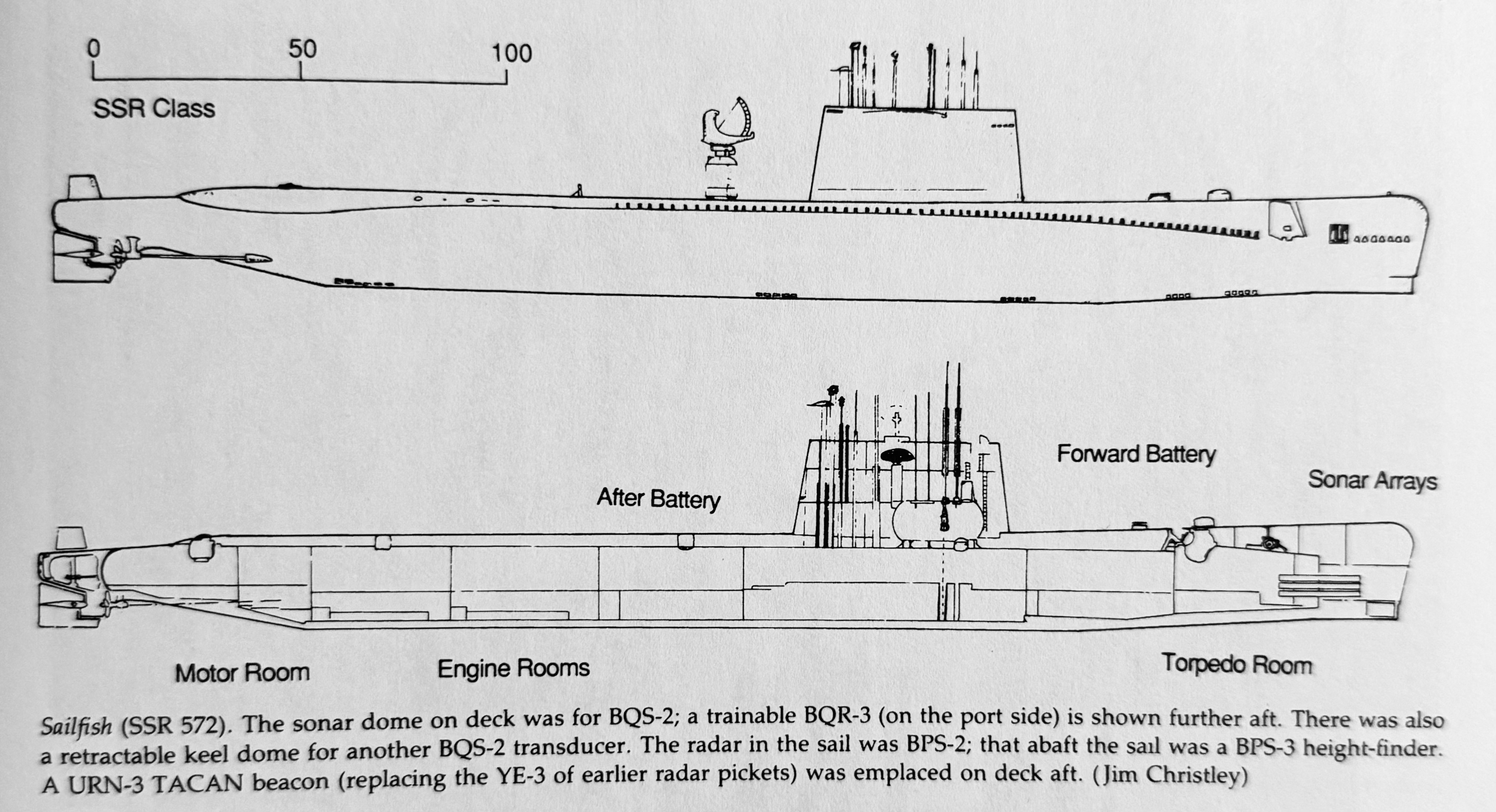
Radar Picket Subs
Fleet boat conversions to radar pickets (the Migraine program) post-WWII were found to have limitations and were nearing the end of their useful service lives by the 1950s. The Sailfish-class boats were the first purpose-built radar picket submarines. Despite being designed for high surface speed to keep up with carrier groups, the results were disappointing, with both boats not making over 20.5 kts when surfaced. Since no existing diesel plants could produce the 20,000 SHP needed for the expected 25 kt surface speed, designers briefly examined the possibility of using gas turbines or steam plants, but this work was abandoned in 1954.31 In the end, only two of this class were commissioned, with USS Sailfish (SSR/SS/AGSS-572) entering service on 14 April 1956, and USS Salmon (SSR/SS/AGSS-573) on 25 August 1956.

USS Triton
Apart from the Tang-class being the first submarines in the U.S. Navy built without conning towers, the use of them didn’t completely disappear since later submarines still had conning towers. The failure of the Sailfish-class submarines to achieve their desired speed pointed the way to nuclear power being the obvious solution. USS Triton (SSRN-586) was originally built as a radar picket submarine and was the last U.S. Navy submarine built with a conning tower inside the sail.
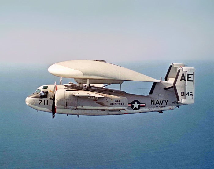
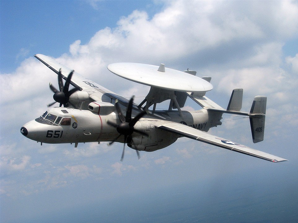
By the time Triton was commissioned on 10 November 1959, the purpose of the radar picket sub died with the introduction of carrier-based airborne early warning (AEW) aircraft like the E-1B Tracer and later E-2 Hawkeye.33 Even then, submarines continued to function as Electronic Intelligence (ELINT) gathering platforms. Due to their covert nature, submarines can gather the remaining 7% of ELINT that overt platforms (satellites and aircraft) can’t obtain.34
With the radar picket submarine concept now dead, Triton no longer had any particular purpose and was too large to be an effective attack sub. A Regulus missile conversion was studied in 1957, and later, a Polaris missile conversion was also studied. However, these would’ve required the removal of her entire front end, including the sail and CIC. A proposal for converting her to a National Emergency Command Post Afloat (NECPA) was also looked at, but all of these ideas were abandoned. Triton is best known for making the first totally submerged around-the-world cruise in 1960, but she was the first nuclear submarine to go into reserve and was decommissioned on 3 May 1969.35
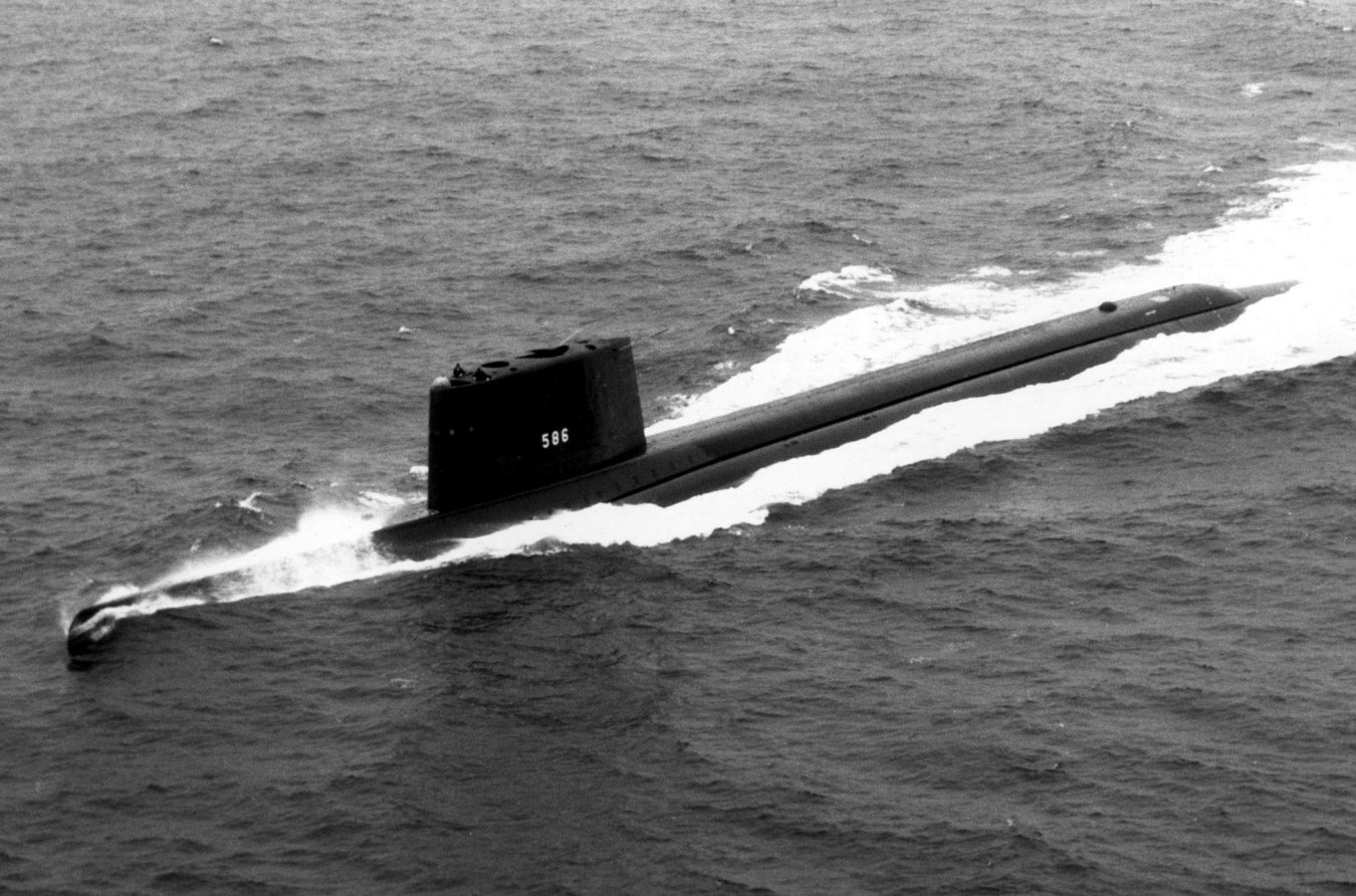
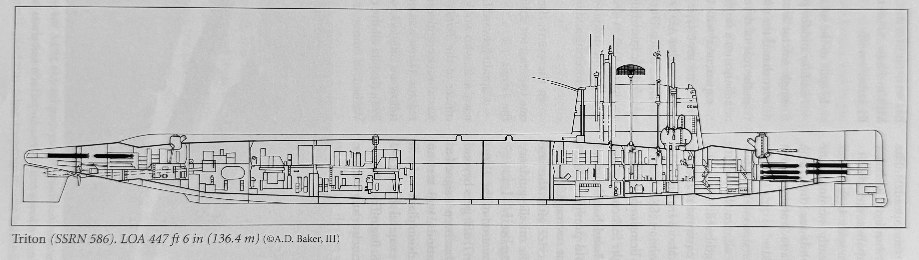
Triton‘s sail was also the largest, in both height and length, on any U.S. submarine in order to house the large SPS-26 three-dimensional electronically scanned radar antenna. The antenna had a massive hoisting cylinder and took up most of the sail’s interior volume. The SPS-26 antenna rotated 90 degrees to the centerline and retracted down into the sail. The SPS-26 was the first of its kind. It could track an aircraft at 65 nm away and flying up to 75,000 ft. However, it was known to be unreliable. Captain “Ned” Beach noted that they seldom used the radar, and most of the operating hours were merely to test and maintain it.38
Barbel-class
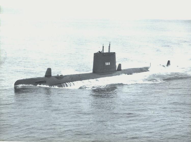
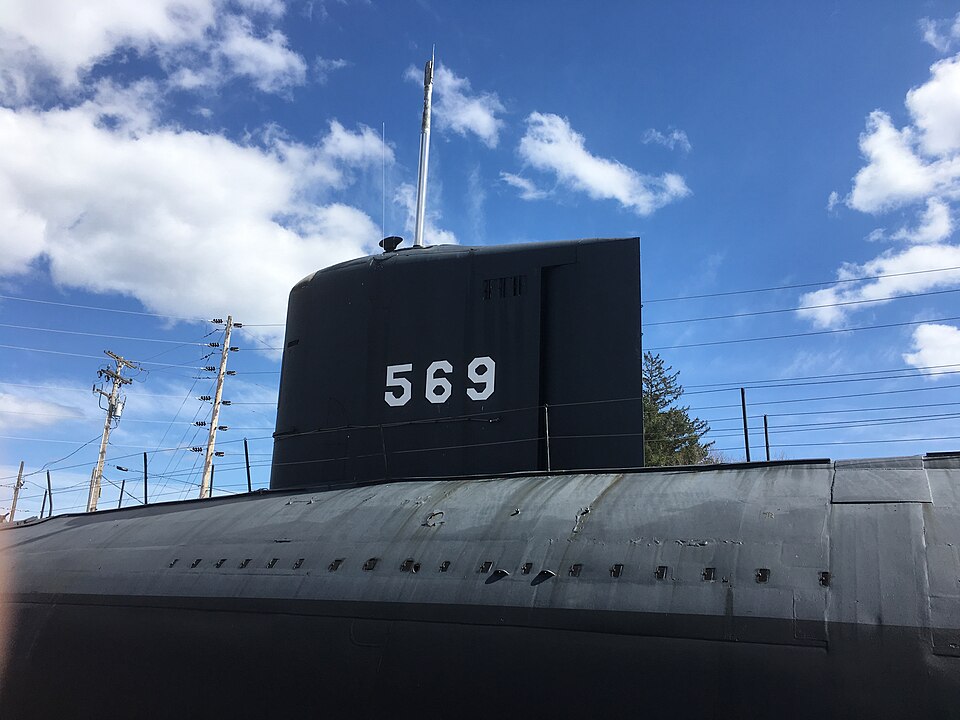
Introduced in 1959, the Barbel-class were the first combat submarines with a teardrop-shaped hull, which was originally pioneered by the experimental USS Albacore (AGSS-569). The Barbels were basically a generation or two newer than the WWII fleet boats, but the streamlined hull design made them much more hydrodynamically efficient and quieter underwater. Following the commissioning of the Tang-class boats in the early 1950s, the three Barbel subs continued the trend of rearranging the superstructure and control room. Now that the conning tower was no longer needed in submarines, the superstructure had fully become a sail, used solely for housing the masts and a bridge cockpit. The bridge is at the forward end, accessible by an access trunk in the control room beneath it. The boat would only be conned from the bridge when on the surface. In fact, the Barbel-class has no such space inside the sail that is analogous to a conning tower on a WWII fleet boat. Apart from the access trunk, the entire sail is free-flooding and is not a habitable space.
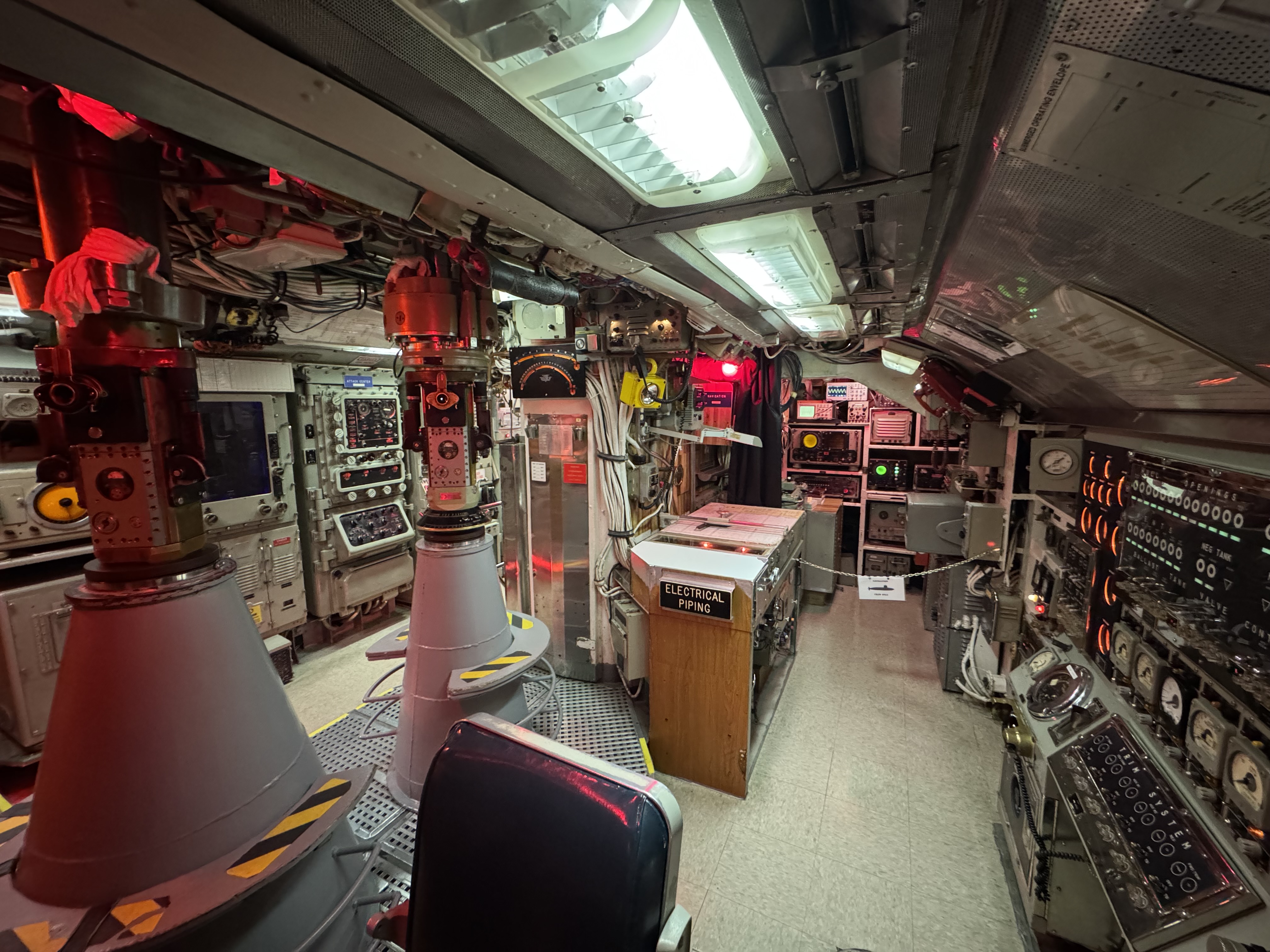
Blueback’s Control Room
While the earlier Tang-class were the first to fully eliminate the pressure hull (conning tower) in the superstructure and move the fire control computers down into the control room, the Barbels were the first U.S. submarines to introduce the more modern control room layout that would look familiar to modern submariners.
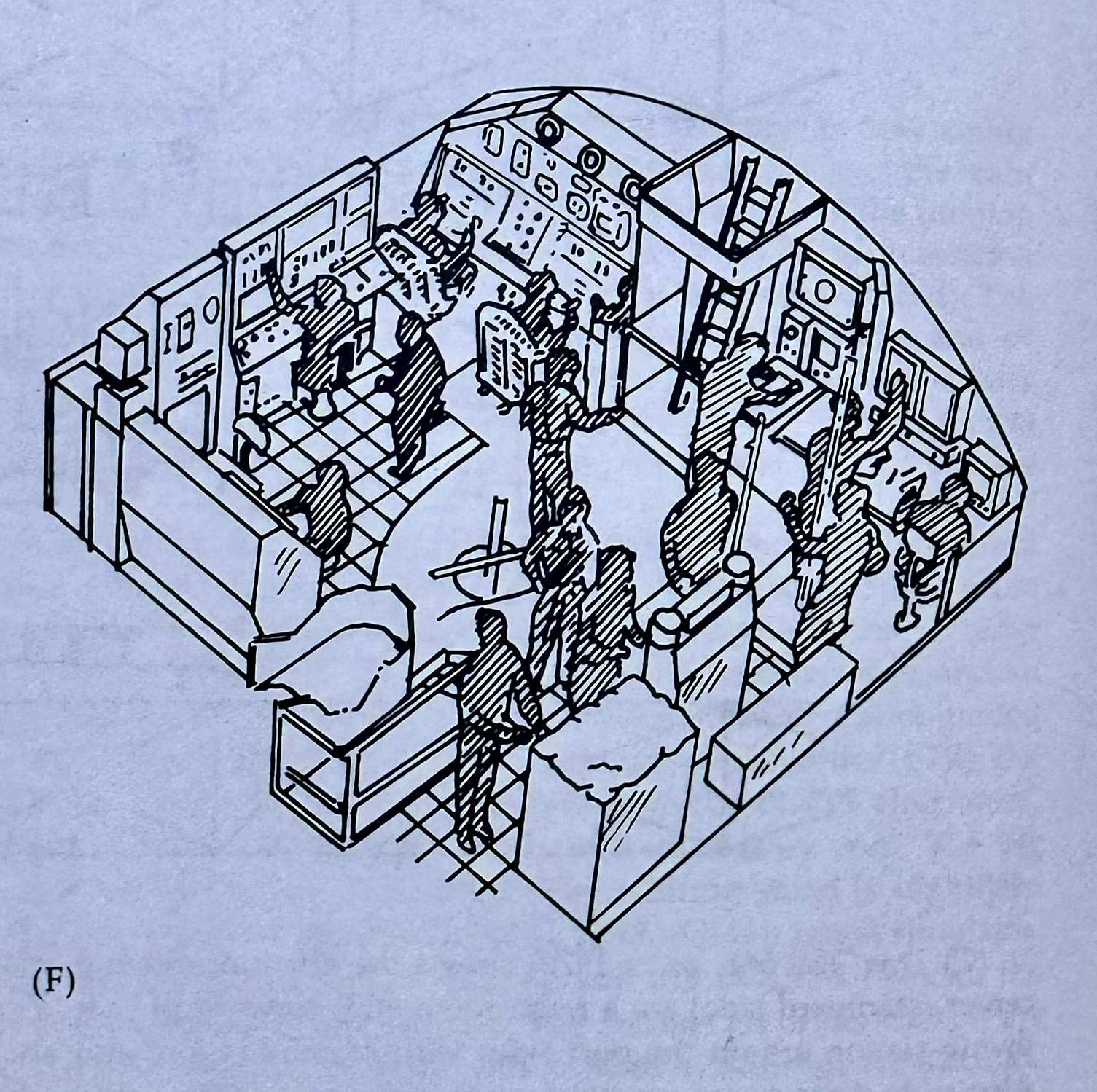
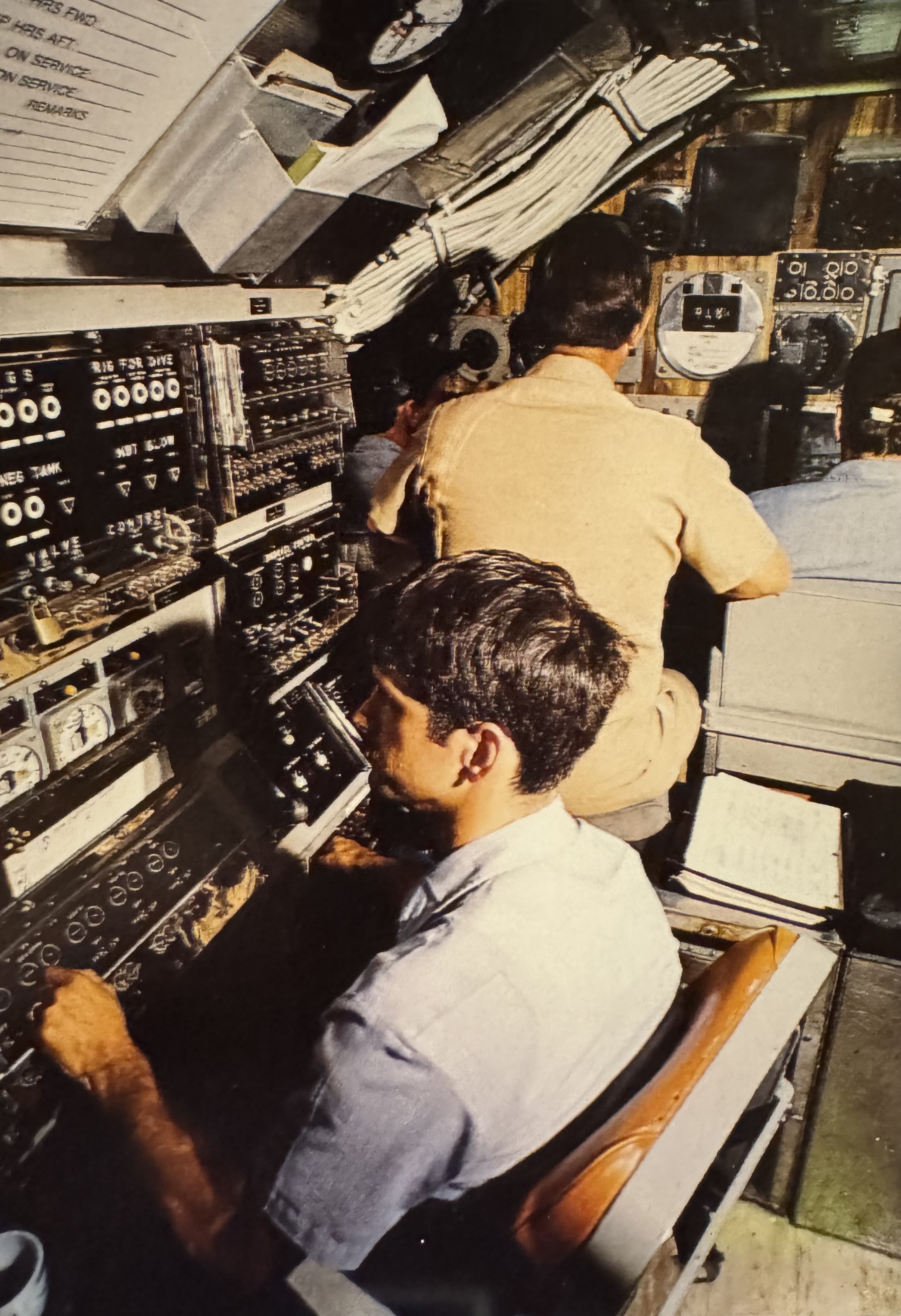
The ladder that leads to the bridge is centered at the forward end of the control room. To the left is the dive station where the helmsman and planesman (AKA pilots) would sit. Behind the pilots on the left side of the control room is the Ballast Control Panel. Further back on the left side is the radar and Electronic Countermeasures/Support measures (ECM/ESM) space. The periscopes are in the center of the control room. There’s a chart table to the right of the ladder that would normally be manned by the weapons officer to plot out attacks.
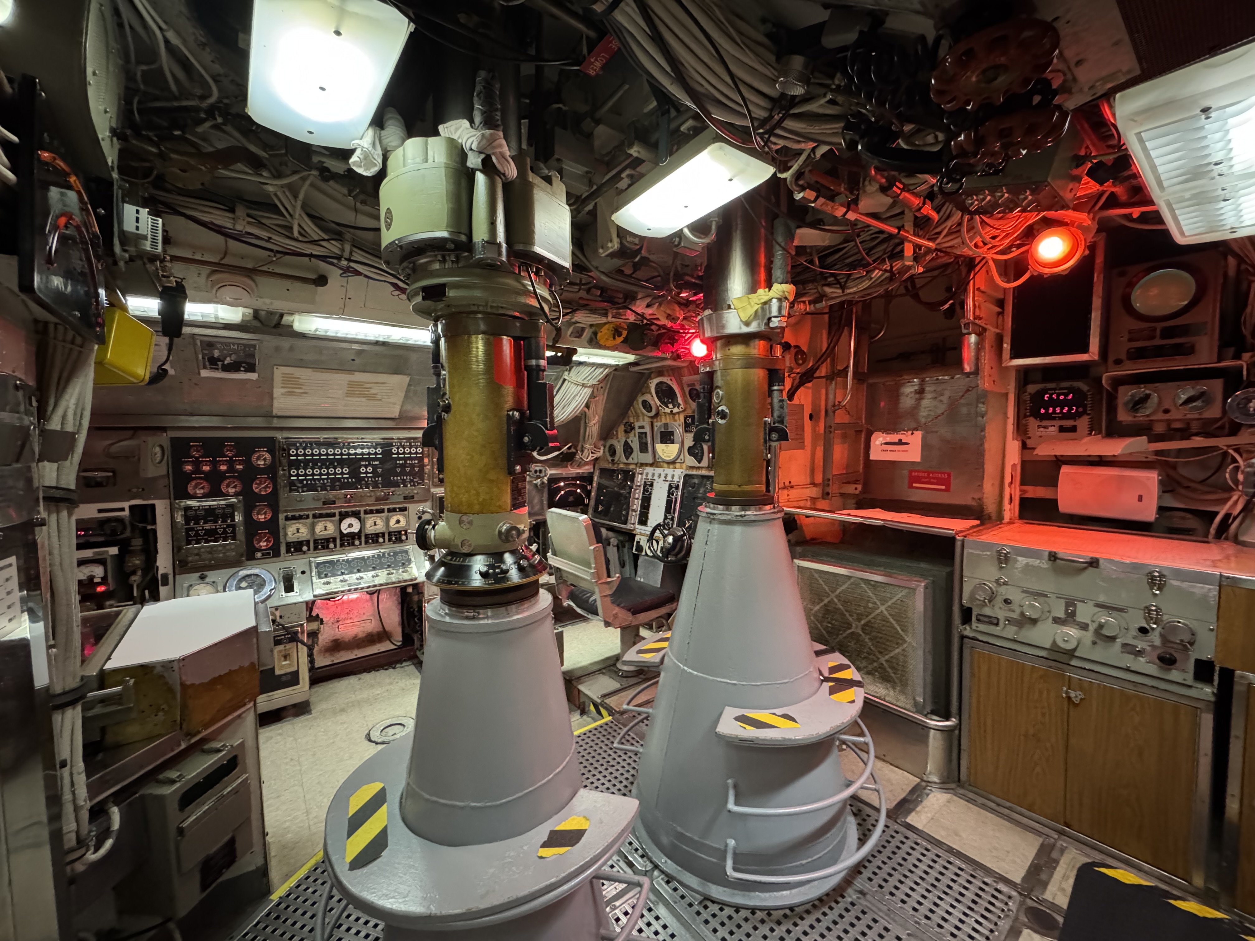
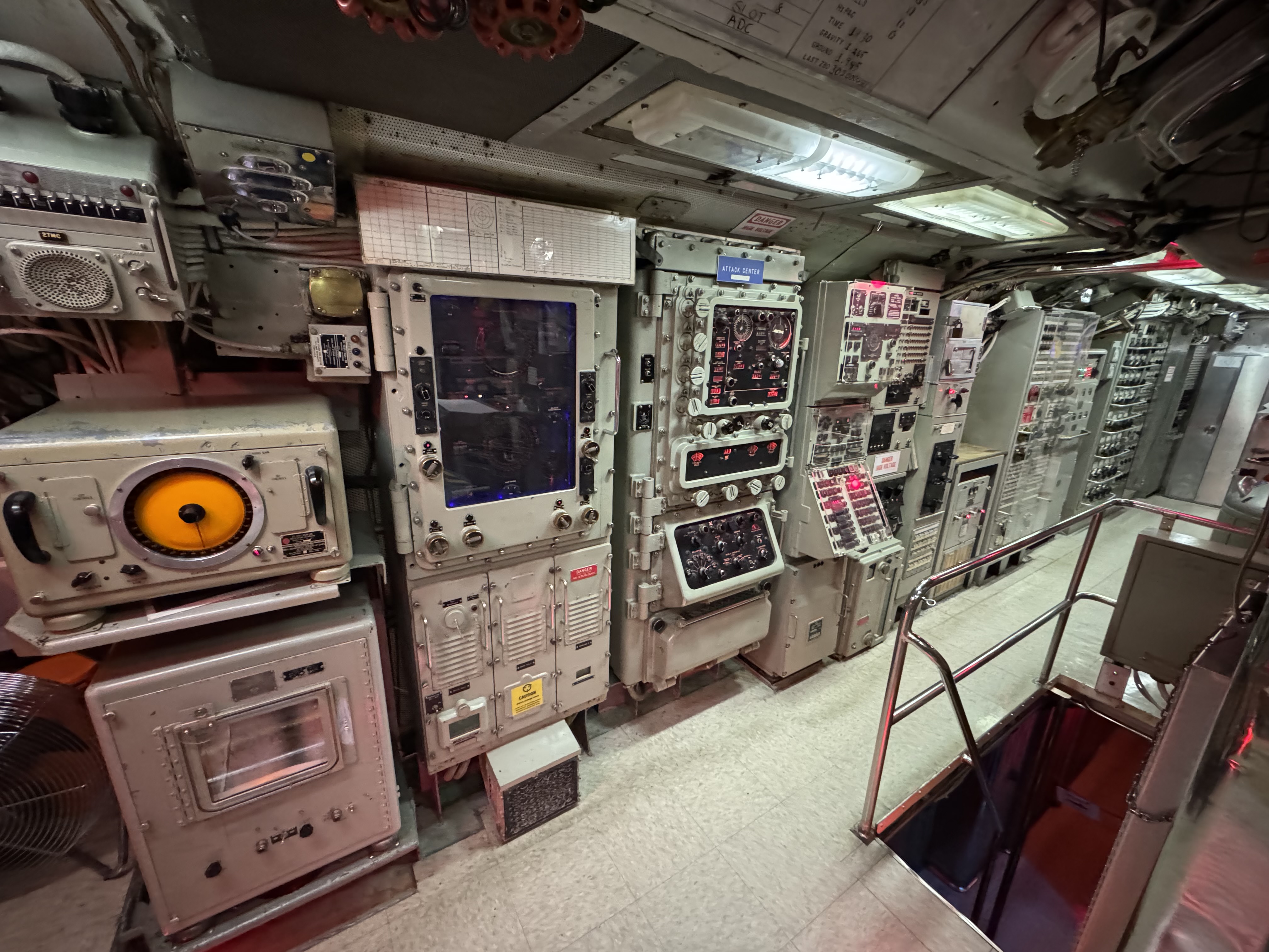
The attack center is on the right side of the control room with the Torpedo Data Computer (TDC) and other fire control equipment.
What’s in Blueback’s Sail?
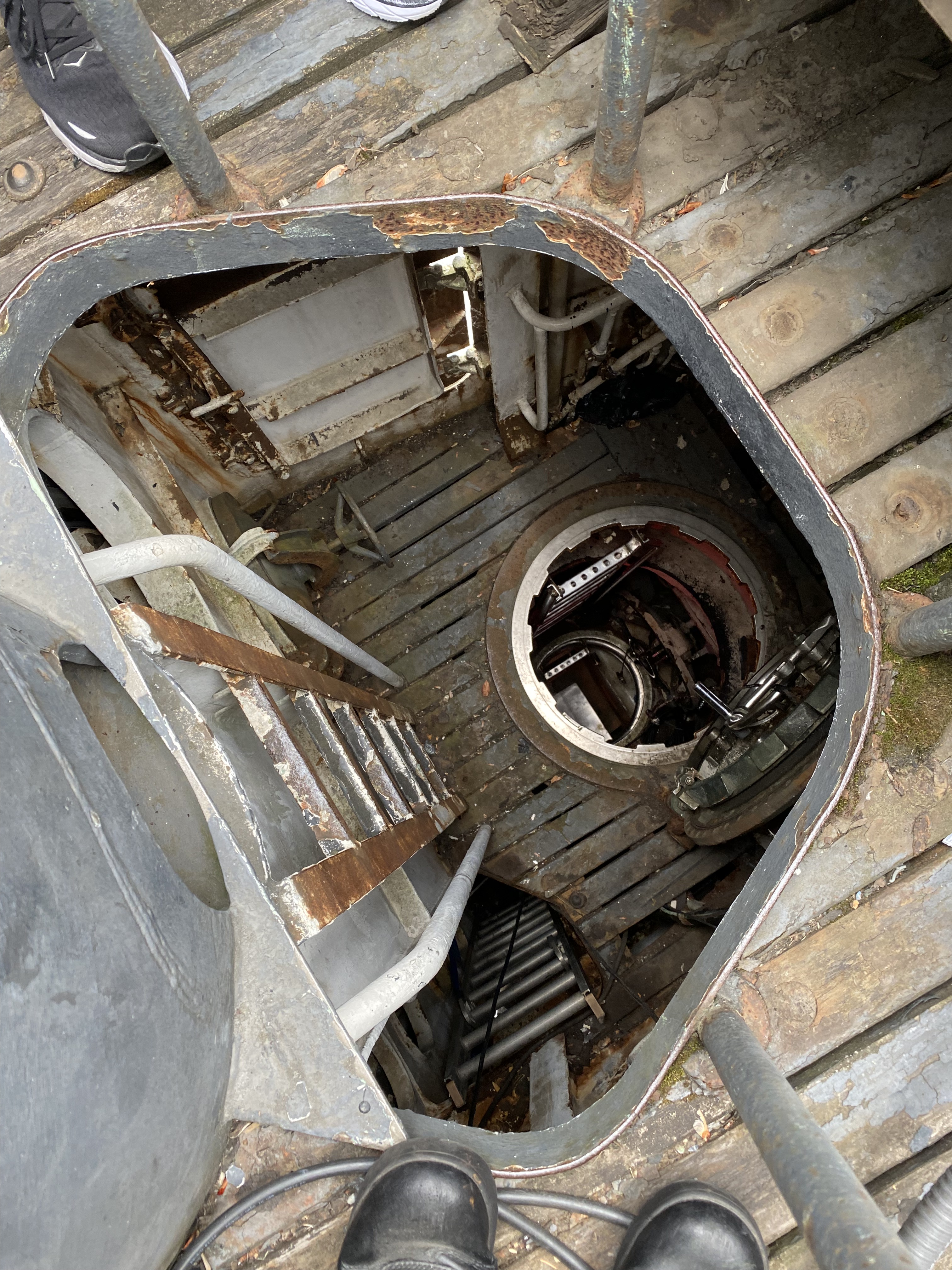
As previously noted, the sail/fairwater of a submarine is really just a streamlined structure to house the boat’s masts and bridge. Blueback‘s sail houses the bridge, bridge access trunk, masts, and hydraulic tilting mechanism for the fairwater planes. The bridge access trunk and hydraulic tilting mechanism are contained within a pressure cubicle that extends from the forward edge of the sail back to frame 26. The Ship Information Book specifies that the sail structure is designed to withstand a wave slap of 1,000 psf from any direction and to minimize noise to the maximum practicable extent. The following drawings and photos illustrate what’s inside Blueback‘s sail. The sail itself is made of mild steel and isn’t designed to break through ice like later submarines.
It should also be noted that the sail itself isn’t a habitable space. The area above and aft of the pressure cubicle floods when the submarine submerges. This is to allow the pressure inside the sail to equalize with the ocean and prevent air bubbles from forming, which would create noise when they pop. There are also various circular and oval plates on the sail to allow maintenance access to the masts, either when they’re extended or retracted. The sail can also be accessed from underneath via the superstructure plating (AKA turtleback).
The masts themselves have hydrofoil fairings and are raised and lowered by hydraulic hoists.
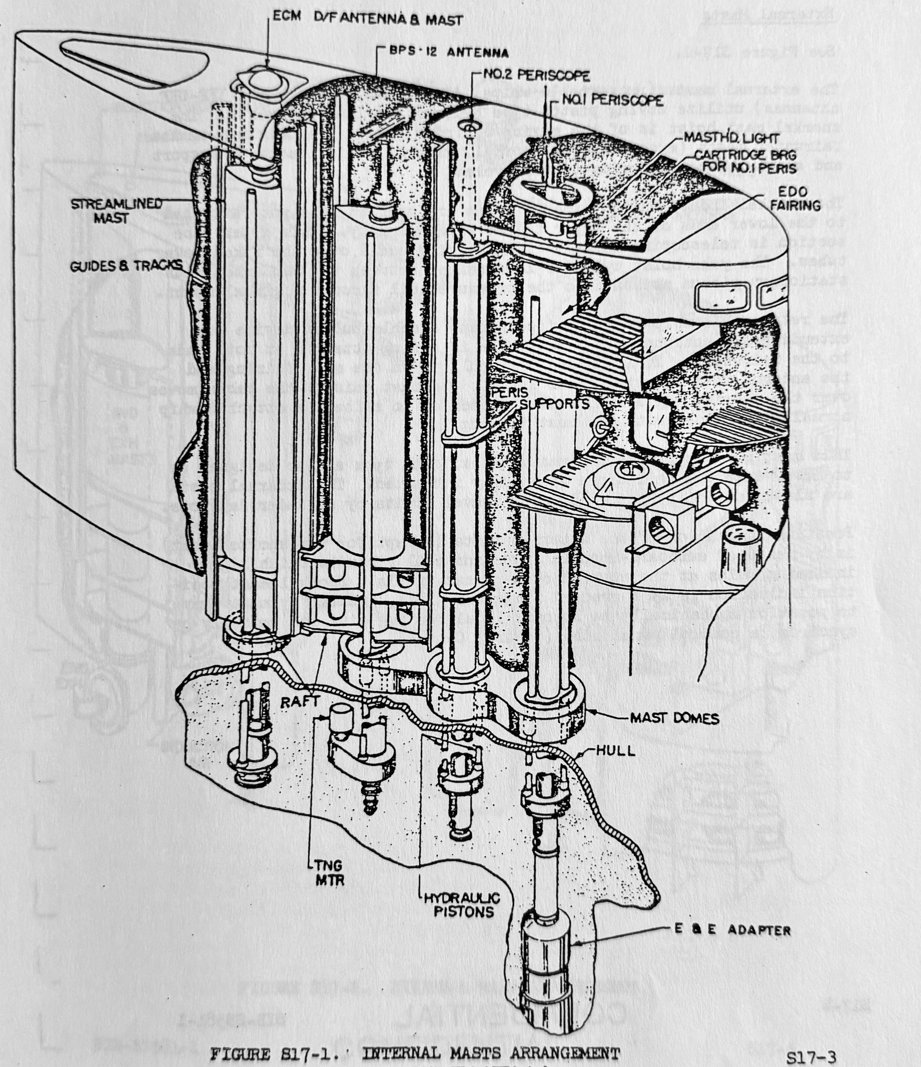
The internal masts are arranged along the centerline of the sail. They are powered by the ship’s main hydraulic system, and both the masts and hydraulic cylinders penetrated the pressure hull via wells. The hydraulic lifting cylinders are attached to lifting rings that carry the masts between them. Vertical guide tracks allow the raft bearings to slide along them. The masts have deceleration valves in the hoist system actuated by mast striker bars, which throttle hydraulic power flow. This slows the masts as they reach the upper and lower limits of their travel. Overflow lines at the tops of the lifting cylinders allow leaking oil to drain inboard to a leakage tank, where it’s drained and disposed of.
The No. 1 periscope is a Type 8, and the No. 2 periscope is a Type 2. Each periscope has a two-cylinder hydraulic lift actuated by manual valves on the periscope stand in the control room. The periscopes penetrate the pressure hull via hull casting seals. The No. 1 scope is powered from the ship’s vital hydraulic system, and the No. 2 scope is powered from the main hydraulic system. The periscope hoisting cylinders are fixed to the sail and supported by the periscope shears. The piston rods are connected to the lifting yoke at the lower ends of the periscope. Deceleration valves are installed in the hydraulic power lines and at the cylinder dashpots to slow the periscopes at the upper and lower limits of their travel. A rubber bumper is also at the bottom of the periscope wells.
There is an independently operated hydrofoil fairing for the No. 1 periscope to reduce vibration and eliminate the plume (AKA feather) when the periscope is raised. A cartridge bearing at the top of the sail is fitted to the fairing to support and guide the periscope as it’s raised and lowered. It also maintains the fairing orientation as the periscope is trained. A masthead light is also mounted on the No. 1 periscope fairing.
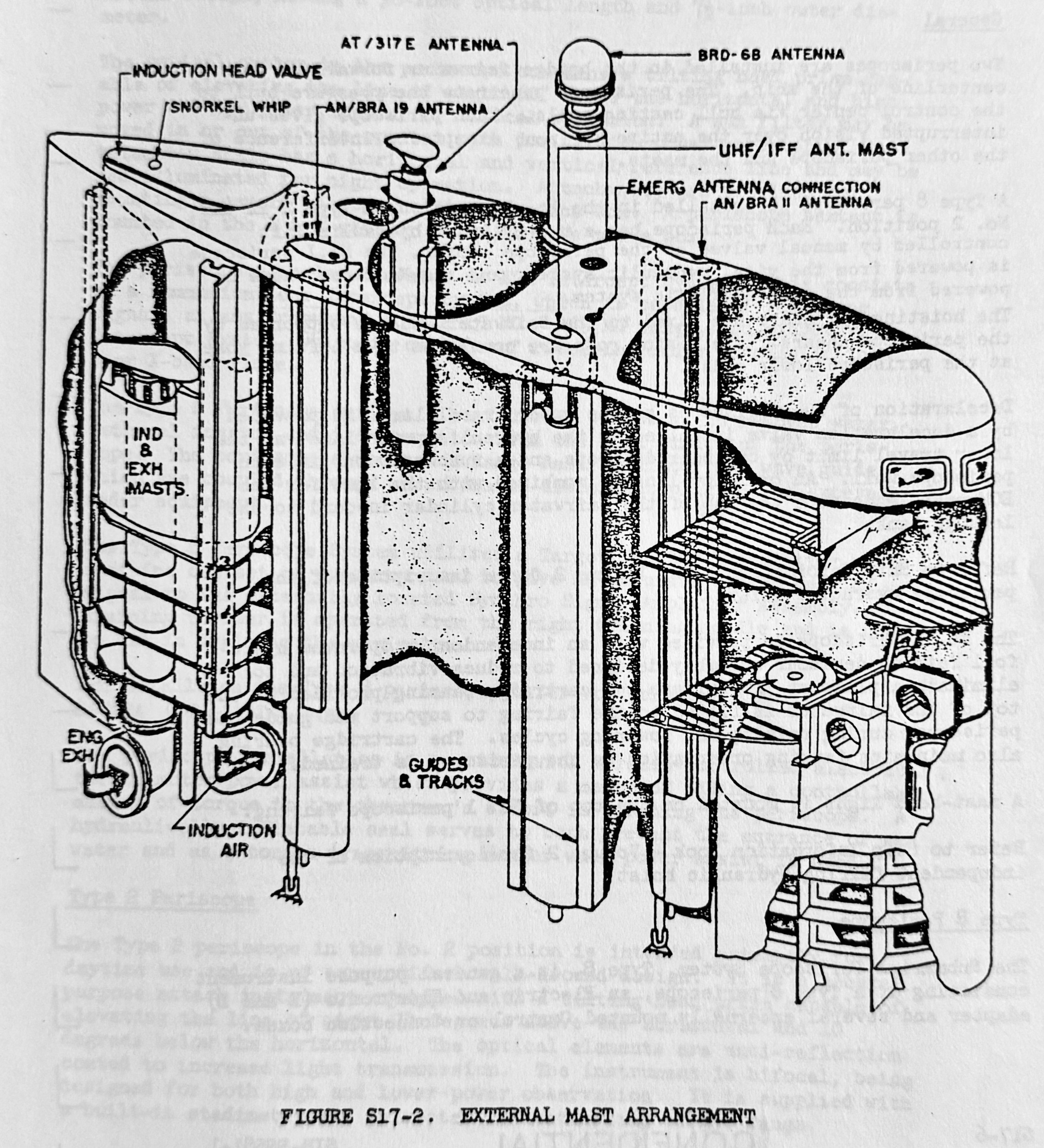
The external masts (and their hydraulic cylinders) are outboard of the centerline and are completely contained within the sail. These masts are powered by hydraulic fluid from the sub’s external power system. The snorkel mast, although arranged on the centerline, is also considered an external mast. These external masts utilize moving piston-type hydraulic cylinder hoists, but the snorkel mast is a moving cylinder type. Except for the snorkel, the external masts ride in guide tracks.
The snorkel induction and exhaust tubes are supported by a yoke attached to the lower ends of the upper faired tube assembly. The upper tube is telescoping and slides in bearing seals over the fixed lower tube. The yoke hoist cylinder is between the two tubes with its stationary piston attached to the pressure hull with a gimbal mount. The whip antennas are extended and lowered using a cable pulley.
All of the masts are designed to lower into the sail crown when fully retracted. Cylinder dashpots slow the external masts at their upper and lower travel limits. With the exception of the periscopes, the indicator lights and mast controls are on a panel in the control room.
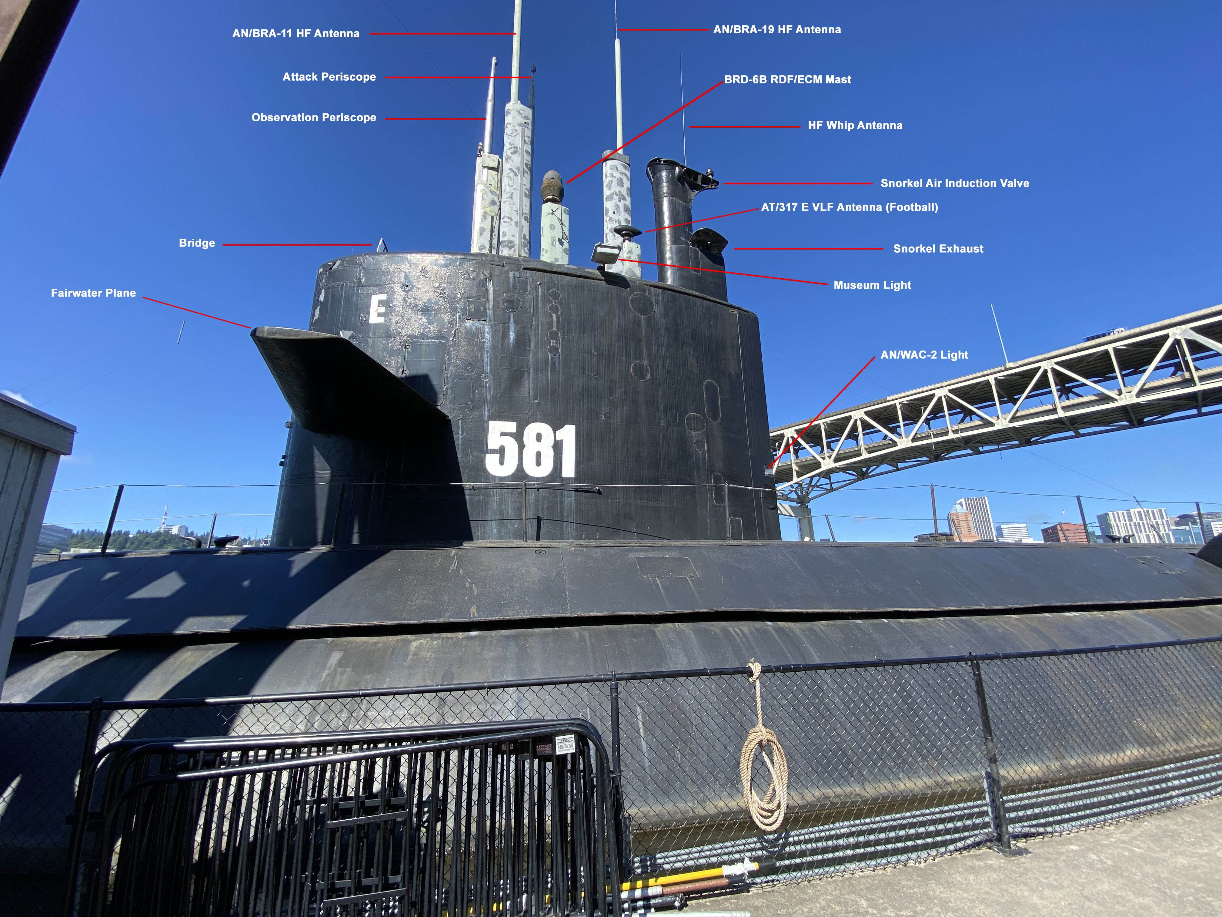
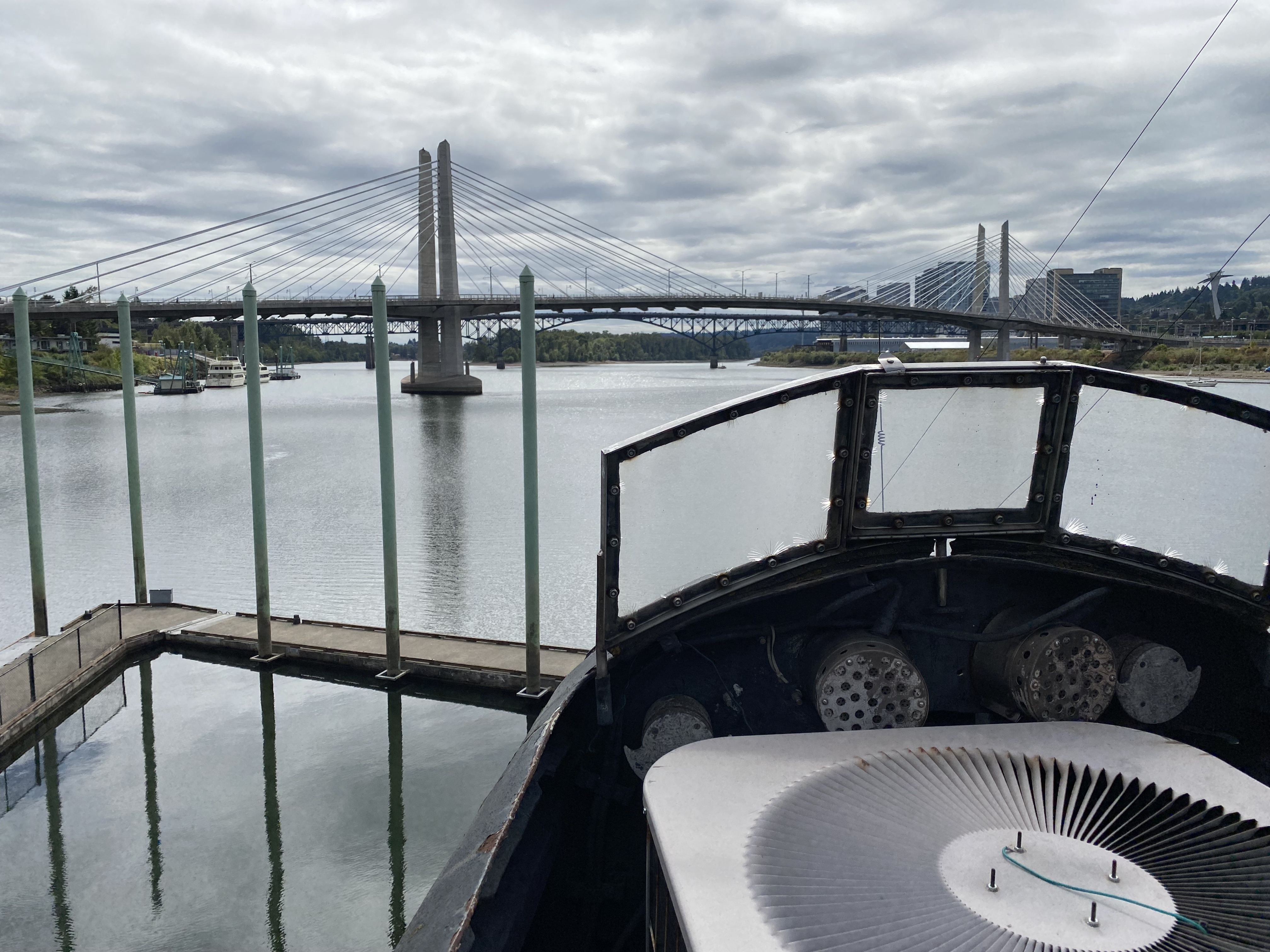
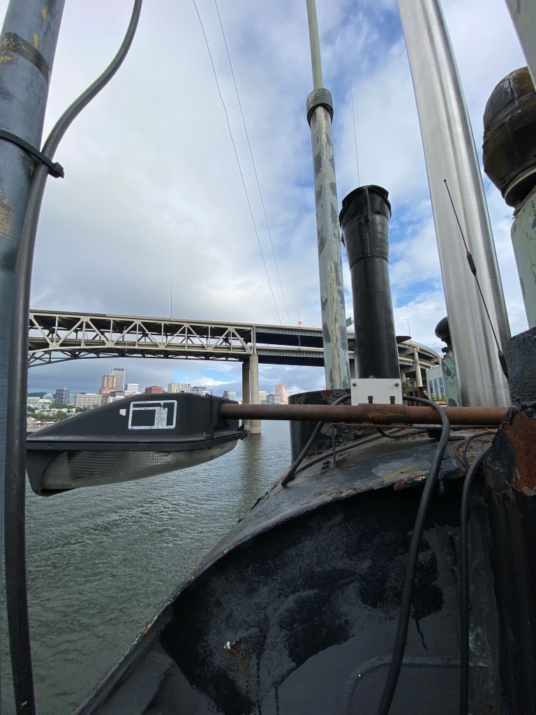
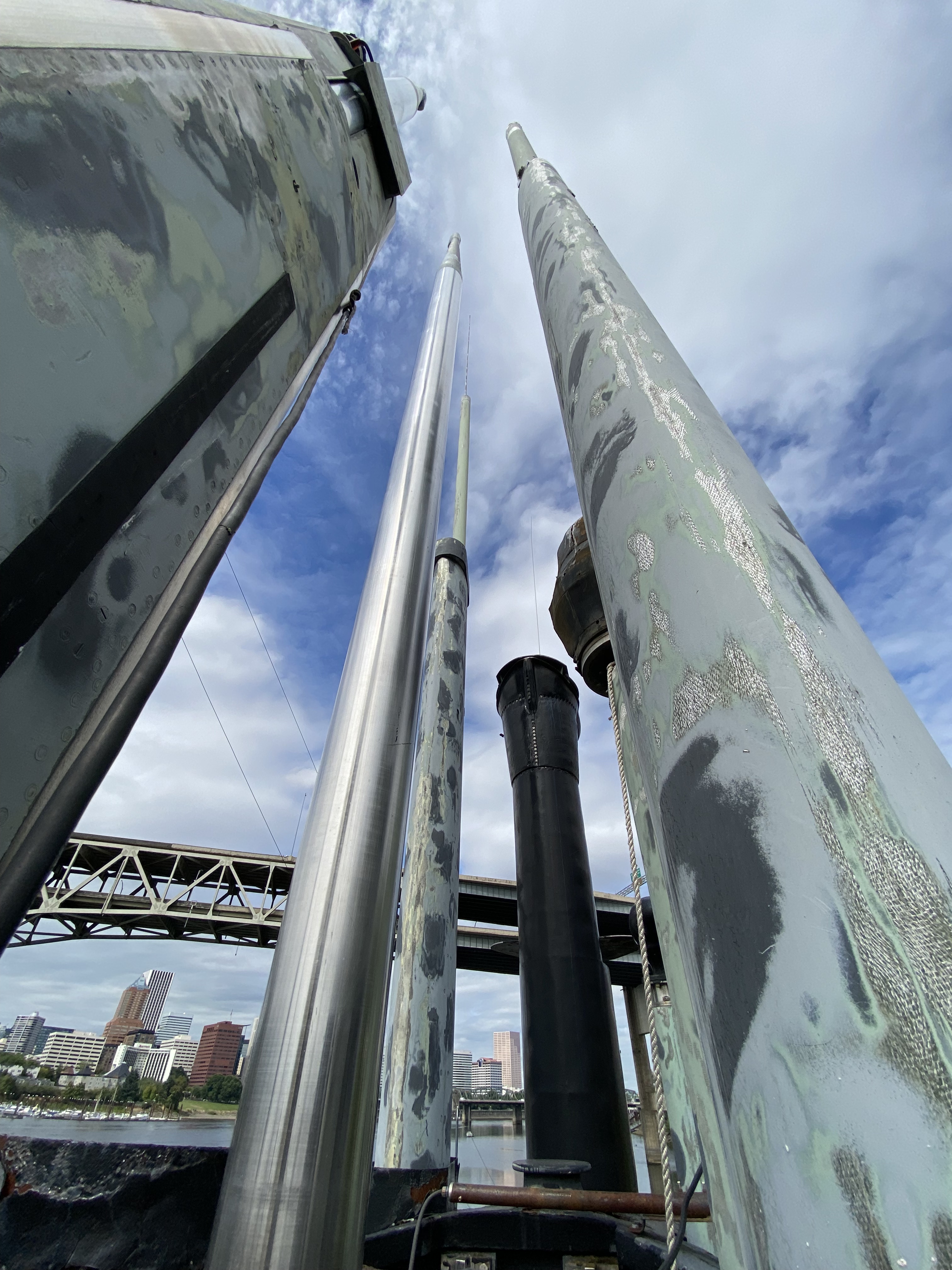
Here are the masts that are currently extended:
- Observation Periscope – The forward-most periscope. It would be the larger of the two, but this is not the original Type 8 observation periscope, from my understanding. (The original observation scope was removed because it had classified ECM intercept equipment on it.)
- Attack Periscope – This is a Type 2 periscope. It is physically smaller in profile to make it harder to detect. It would also have an Ultra High Frequency/Identification Friend or Foe (UHF/IFF) antenna operating in the 200 – 500 MHz frequency range. (This is also not the original attack scope.)
- AN/BRA-11 & AN/BRA-19 – The BRA-11 is a helical antenna, and the BRA-19 is a telescoping whip antenna. These are High-Frequency (HF) transmitters operating in the 2 – 32 MHz frequency range. Both are capable of receiving in the low, medium, and high-frequency ranges.
- BRD-6B – This is a Radio Direction Finder (RDF) and Electronic Countermeasures (ECM) mast. It can be used for navigation and radio surveillance.
- AT/317E (AKA the football) – This is a Very Low Frequency (VLF) loop antenna capable of receiving signals up to 90 feet underwater.
- Snorkel – This contains the air induction valve at the very top and the exhaust just under the plate (AKA batwings) about halfway down. There is also an AT-497/UHF whip antenna on the top of the snorkel.
There are two more masts in the sail that are currently not raised. One would be the AN/BPS-12 surface search/navigation radar antenna next to the BRD-6B antenna. The other would be the AN/BLR ECM/ESM mast (for radar interception and direction finding) between the AT/317E and BRA-19 antennas. This mast is distinct from the BRD-6B antenna. The reason these masts are no longer extended is that they lost hydraulic pressure during Blueback‘s last drydocking in 1998. (Further discussion of the ECM/ESM system below.)
An access trunk leads from the control room up to the navigation level and the bridge at the front of the sail. From the control room all the way up to the bridge, it’s a roughly 20 to 25-foot climb up the ladders.


Other Stories of Blueback’s Sail
As mentioned, the sail interior isn’t a habitable space, and inside the sail is filled with masts, hydraulic cylinders, and other machinery. It’s not exactly a safe place to be, even when the submarine is on the surface. Two stories from Blueback’s deck logs illustrate this.
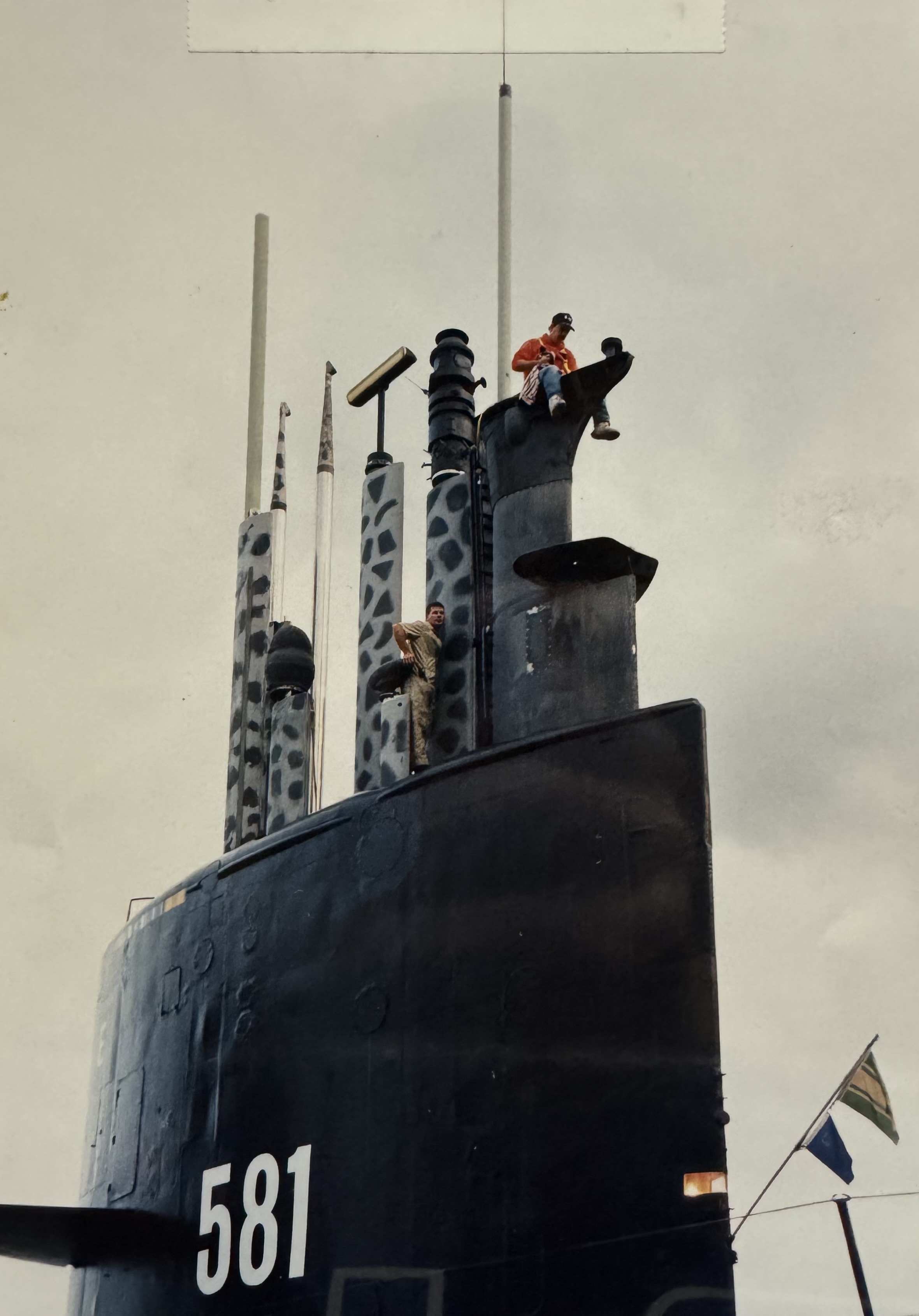
On Wednesday, 18 February 1970, Blueback was surfaced, when around 1920, QM3 Verdel M. Meyers was working on adjusting the magnesyn compass in the sail, and his right foot got inadvertently caught in the hydraulic ram for the sail planes. The movement of the ram caused a “traumatic amputation of his right toes.” OUCH! The corpsman administered emergency medical treatment, and around 2005, a Coast Guard helicopter arrived to medevac Meyers from the submarine to Tripler Army General Hospital for further treatment. The helo transfer was completed around 2024. Blueback then continued on her way.
Why exactly the sail planes’ hydraulic ram was moving when the submarine was surfaced is unknown. Whether it was intentional or accidental is also unknown. They should’ve told the helmsman not to move the sail planes or locked that function on his control yoke. Especially when someone was working up in that space! Additionally, what kind of emergency treatment the corpsman administered to Meyers is unknown, but the lore amongst the tour guides says it was the partial amputation of what was left of his right toes. He could’ve very well simply bandaged his foot up. For a while, I mistakenly believed that this foot amputation was the result of an officer or sailor getting his foot caught in the periscope well as the periscope retracted down, but the deck log shows that this wasn’t what happened. In any case, Verdel Meyers ended that day five toes shorter on his right foot.
The second story takes place in Berth 2 of the U.S. Naval Repair Facility in Yokosuka, Japan, on Thursday, 11 June 1970. Around 0910, Kamoi Masakichi, a Japanese civilian yardworker with Shop 72, was working on the ECM mast in the sail when he was fatally injured. He was pronounced dead at the scene, and his remains were removed at 1053 and transferred to Yokosuka Naval Hospital. The exact cause of Kamoi’s death, as he was working on the ECM mast, is unknown, but hearsay from former Blueback crewmembers we’ve met said that he was crushed when the mast was inadvertently lowered. (He could’ve simply been electrocuted for all we know.)
Suffice it to say that 1970 was not a good year to be working in Blueback‘s sail.
The Modern Sail
In addition to housing the masts, the sail serves some additional purposes, as well.
- It acts as a sort of vertical stabilizer while the submarine is submerged.
- Provides a structure for mounting a submarine’s forward dive planes instead of on the bow.
- When properly reinforced, it allows a submarine to break through ice in polar regions. (However, not all submarine sails have this capability.)
- Provides additional freeboard above the water for the bridge, where the boat can be conned from when on the surface, as well as space for force protection when the sub is transiting on the surface.
Vertical Stabilizer
As has been noted, the superstructure and sail of a submarine tend to create a significant amount of drag and perturbation in the water. While it does act as a sort of vertical stabilizer, it has another downside. Underwater tests with USS Albacore (AGSS-569) noted that when the boat would turn, the sail acted as a massive hydroplane and could cause a snap roll with the boat flipping over to one side. In this orientation, the sail and the rudder would now act as diving planes, which were far larger than the normal control surfaces, and the result would inevitably be a dive with any turn. The faster the speed, the worse the problem was. To help alleviate this problem, Albacore had a large dorsal rudder on the aft end of the sail, which was controlled by foot pedals at the pilot’s station. The problem was that this put a great amount of stress on the sail structure, and it was rarely used. It was found that the sail rudder and stern rudder also tended to act as brakes.41
One of many quieting features of the one-off submarine USS Narwhal (SSN-671) was moving the sail further aft. It was found that if the sail was placed over the transition from the forward nose cone and the main cylinder of the pressure hull, it would create noise, so the sail was placed further back to prevent that.43
Sail/Fairwater Planes
Some submarines have dive planes on either side of the sail, which are called sail/fairwater planes. Since most sails are situated roughly amidships or just forward of amidships, the sail planes provide some modest depth control when the submarine is underwater. (Obviously, sail planes serve no purpose when the submarine is surfaced.)
The Skipjack-class began a notable trend in U.S. attack subs of putting dive planes on the sail. The dive planes were moved from the sail to again become bow planes with the introduction of the Improved Los Angeles-class, starting with USS San Juan (SSN-751). The ballistic missile boats from the George Washington-class onward followed the same trend.
The benefits of moving the planes to the sail were that this eliminated the turbulence and machinery noise around a submarine’s bow-mounted sonar. Sail planes are also better at controlling depth when a sub is near the surface, which is important for submarines launching cruise and ballistic missiles. (The upcoming Columbia-class ballistic missile boats, which will replace the Ohio-class, will maintain the use of sail planes.) The use of sail planes also had the unexpected benefit of allowing a submarine to slowly change depth without changing its trim angle, which could result in significant changes in upward or downward momentum.44

The Thresher/Permit class notably had smaller sails. While they had a surfaced displacement (~3,750 tons) about 22% larger than the earlier Skipjack-class, their sails were about half the size of those subs. The smaller sail size was the result of deleting some masts and, correspondingly, some of the electronic intelligence capabilities of these boats. There were proponents of completely deleting the sail to reduce underwater drag, but the sail was needed to mount the fairwater planes, house the masts, and provide space for the bridge to navigate the submarine on the surface.45
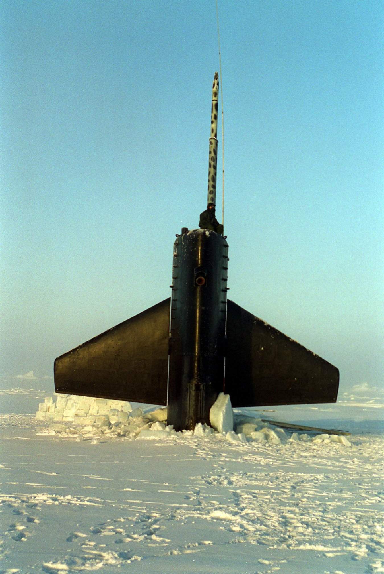
Under Ice Operations
Under ice operations are extremely challenging for submarines. The Arctic Ocean covers some 3.3 million square miles (8.5 million square kilometers) – roughly the same size as the United States – most of which is covered in ice pack, which can vary depending on the season. The depth of the ocean can also vary considerably. Some areas can be very shallow, and others over 6,000 feet (1,830 meters) deep. The ice itself can also project downward from 6 – 20 feet, with some being observed to project down to 162 feet. Effectively, this creates a ceiling of ice with the submarine sandwiched between the ice and the seafloor. Some accounts have U.S. submarines travelling only 25 feet above the seafloor with only seven feet of clearance between the top of the sail and the pack ice. The ice and the marine life in the region also create a very unique and challenging soundscape for sonar operators, as well as for acoustically guided torpedoes. At times it’s very calm, and at other times the ice is moving, creating an incessant creaking noise. Low salinity in the area and currents of cold and warm water also affect sound propagation through the area.46
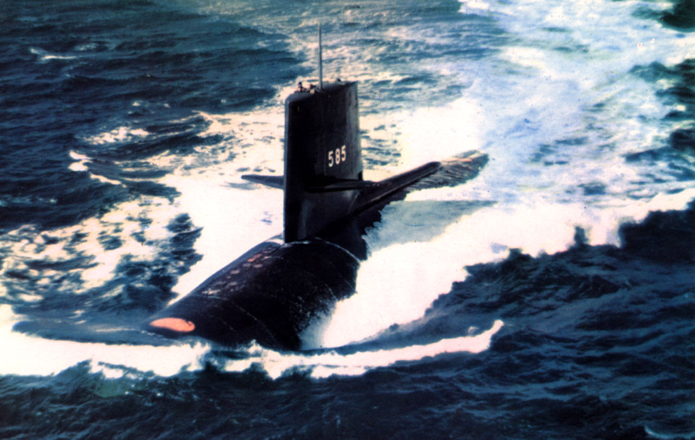
USS Skate (SSN-578) did several under-ice cruises, surfacing nine times through the ice pack, and became the second submarine to reach the North Pole on 11 August 1958 (the first was USS Nautilus). On Skate‘s second voyage to the Arctic, she became the first submarine to surface through the ice at the North Pole on 17 March 1959. The four Skate-class subs were engaged in Arctic research and seafloor mapping for many years. They had to be fitted with special fathometers, ice detecting sonars, and reinforced sails to allow them to break through thin ice.47
The Sturgeon-class subs, which followed the Thresher/Permit-class, were some 510 tons larger and featured improved quieting features. They also reintroduced a larger sail that could house the antennas for electronic intelligence gathering that the latter lacked. The sail planes of these submarines could also be rotated 90 degrees to reduce damage when breaking through the ice pack.48
Although not explicitly designed for it, one former sailor aboard the Los Angeles-class boat, USS Memphis (SSN-691), told me that his boat could break through a couple of feet of ice by angling the boat upwards and using the bow and the forward corner of the sail to punch through the ice pack.
Force Protection
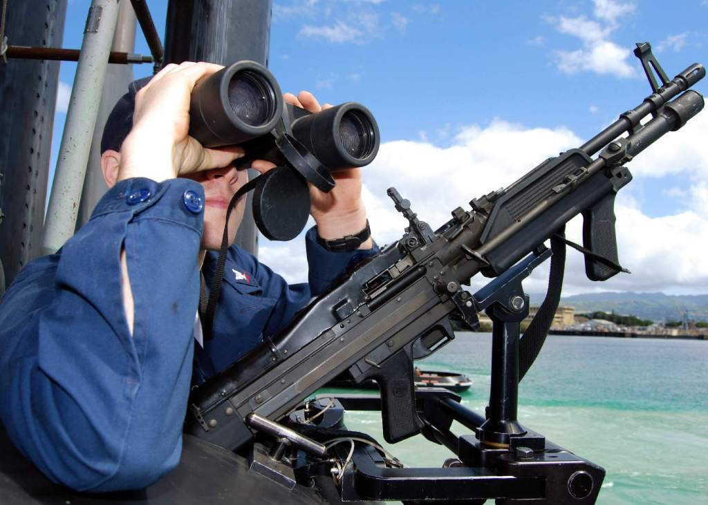
A submarine is most vulnerable when on the surface, transiting in and out of port. The sail has some limited space for lookouts, and some will be armed with weapons to provide force protection and defense against any approaching hostile surface craft.
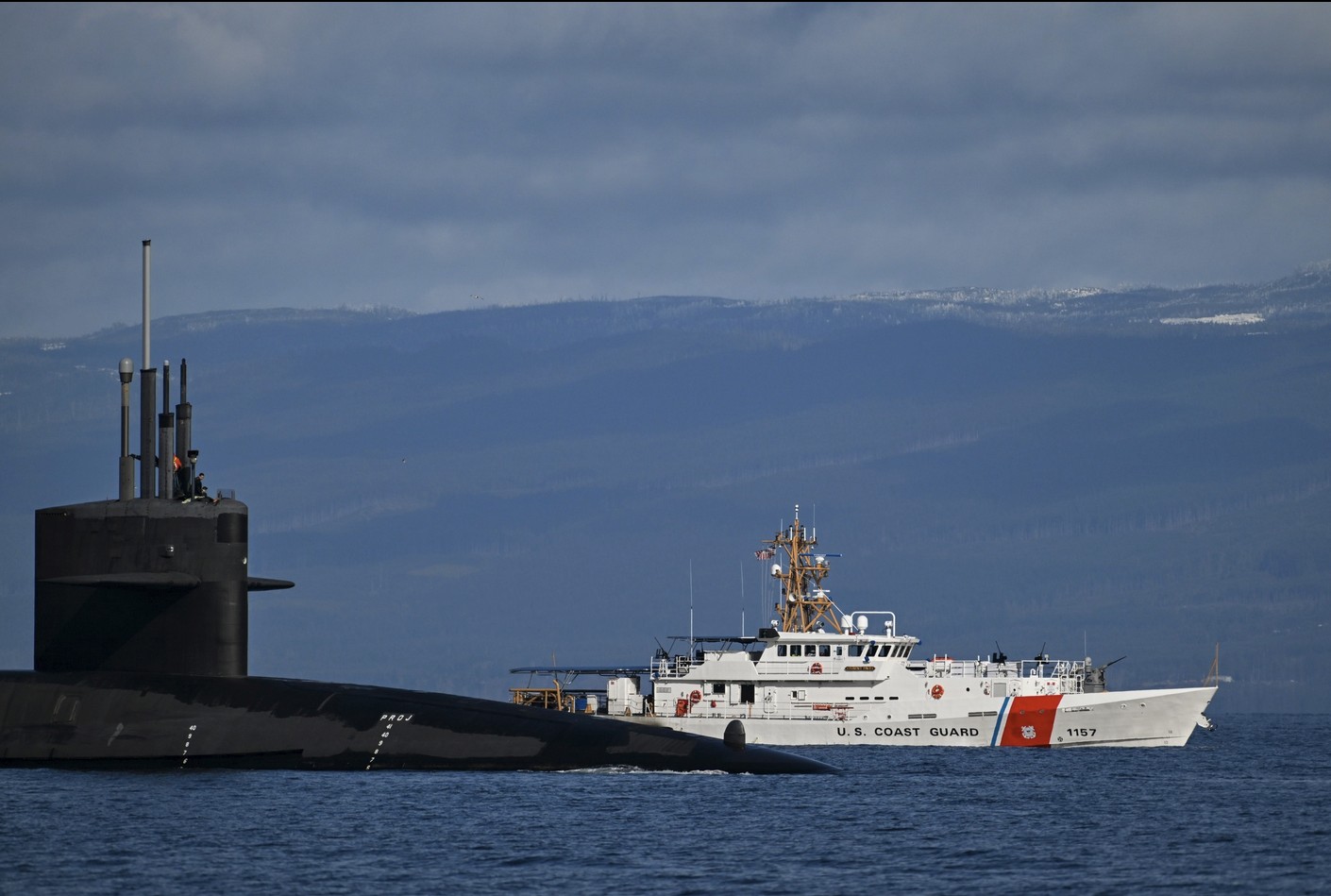
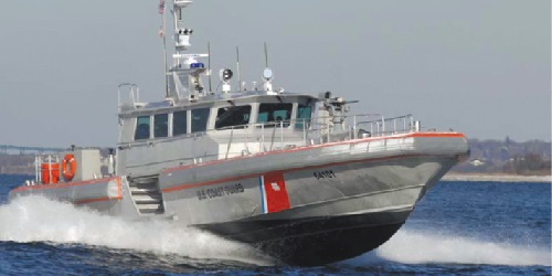
At sub bases with ballistic missile submarines, like Bangor, Washington, or King’s Bay, Georgia, additional protection is provided by a U.S. Coast Guard Maritime Force Protection Unit (MFPU). These are single-mission units with about 150 personnel and several types of boats and cutters with the sole purpose of defending the ballistic missile boats as they are on the surface and moving in and out of port to and from their patrol stations.
U.S. naval vessels have a protective zone around them, and boats are required to remain 500 yards or more from them. If within 500 yards, they must slow down to their lowest navigable speed. They also must not approach within 100 yards of a naval vessel without contacting the vessel or its Coast Guard escort. Some areas feature an extended security zone, such as when a submarine is in Puget Sound, where the security zone is 1,000 yards around the submarine.
From the Seawolf-class onward, modern U.S. submarine sails also feature a curved area on the forward edge of the sail where it meets the hull. This is known as a fillet; the purpose of which is to reduce hydrodynamic drag and vortices when water encounters the sail. In addition to attack boats, fillets will also appear on the sails of the upcoming Columbia-class ballistic missile subs.


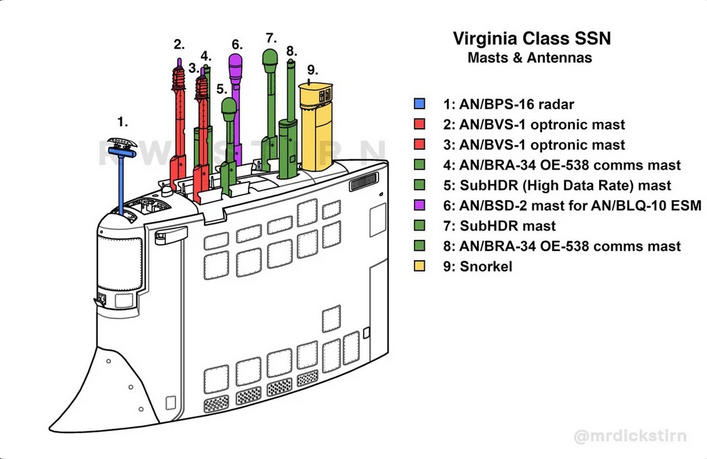
As many articles have also noted, Virginia-class submarines use photonics (AKA optronics) masts rather than traditional optical periscopes. This decreases the need for the periscope wells to penetrate the hull of the submarine, and the information from the photonics masts can be fiber-optically wired to digital screens in the control room, which is also situated lower inside the hull of the boat.
Soviet/Russian Submarine Sails
Many of the Soviet/Russian submarines had very unique designs, which is especially true when compared to American submarine designs that were very conservative in nature. This uniqueness extended to the use of the sails on Soviet subs. The following will cover some of the more unique sail designs of Soviet subs and isn’t intended to be all-inclusive.
The U.S. Navy initially fitted cruise missiles to submarines for strategic attack, but switched to ballistic missiles for that purpose. In contrast, the Soviet Navy continued to develop both cruise missiles and ballistic missiles for the strategic role. In particular, the Soviets developed a canister from cruise missiles that could be mounted on the deck of a submarine or a warship to serve as both a storage and launch tube for the missile.52
The SS-N-3c (P-5) Shaddock missile was developed in the mid-1950s as a strategic nuclear cruise missile. (It was a contemporary of the U.S. Regulus missile.) The missile could carry either a 350 KT (possibly even 800 KT) nuclear warhead or a 2,200 lbs. conventional warhead.53 Successful tests of the Shaddock missile demonstrated a supersonic speed (Mach 1.2) and a range of about 250 – 300 nm. The first operational deployment of the Shaddock missile was on the modified Whiskey Twin-Cylinder (Project 644) submarines. Six of these boats were converted in 1960 and had a pair of missile canisters fitted aft of the superstructure. These canisters would elevate and fire the missiles over the stern.54
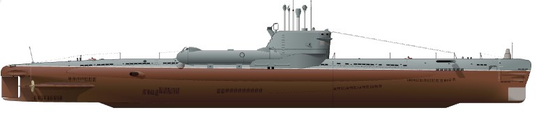
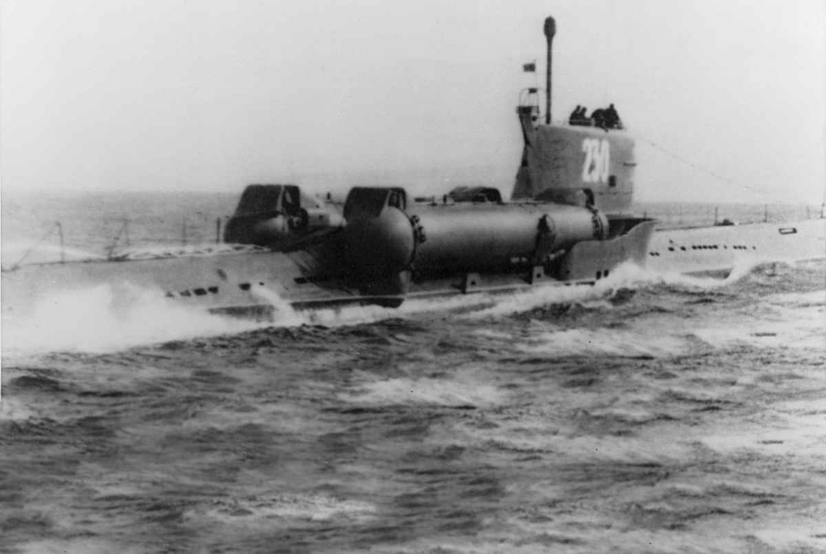
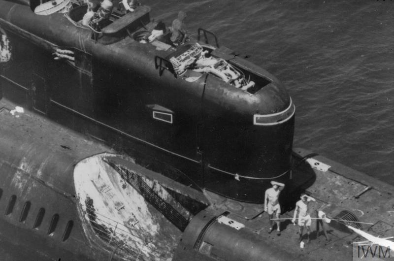
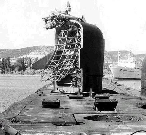
Further work on cruise missile submarines continued with the Echo II-class (Project 675). Design work for the Echo II-class submarines began in 1958. These nuclear-powered subs had a length of 378.5 feet and a submerged displacement of 5,737 tons. To fire its missiles, the submarine had to surface, and the eight missile canisters elevated upwards 15 degrees to fire. One unique thing about these submarines was that the entire front portion of the sail rotated 180 degrees to expose the Front Door/Front Piece radar, which would guide the missile to the target. This also necessitated moving the bridge cockpit further back to the middle of the sail.55
On a side note, the Soviet development of cruise missile submarines armed with anti-ship missiles designed to attack U.S. aircraft carriers with nuclear strike-capable aircraft resulted in the construction of some 50 cruise missile subs of the Juliett, Echo I, and Echo II classes. Some of these were deployed as far away as the Caribbean. Unlike the U.S. Navy, cruise missile submarines were much more prevalent with the Soviet Navy. The U.S. response was to increase its tactical anti-submarine warfare capabilities and develop the Harpoon anti-ship missile, which aircraft could use to attack these submarines while they were surfaced and firing their missiles.57
Sail designs continued to change, and the Soviets clearly weren’t very interested in aesthetics. The Whiskey Long Bin (Project 665) subs had what has to be some of the ugliest sails ever put on a submarine. The term Long Bin was the NATO designation and referred to the enlarged fairwater, which housed four forward-firing Shaddock launch tubes fixed at 14 degrees of elevation. Six of these subs were built at the Gor’kiy and Baltic shipyards between 1961-63.58 One can only imagine that the massive superstructure on these boats wasn’t terribly hydrodynamically efficient.
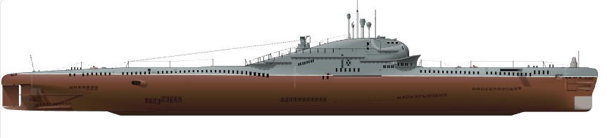
The superstructures on Soviet subs weren’t limited to housing cruise missiles. The Zulu and Golf classes (among others, like the Hotel-class) had ballistic missile tubes mounted vertically inside the sail. These missile tubes extended from the top of the sail all the way down through the pressure hull.
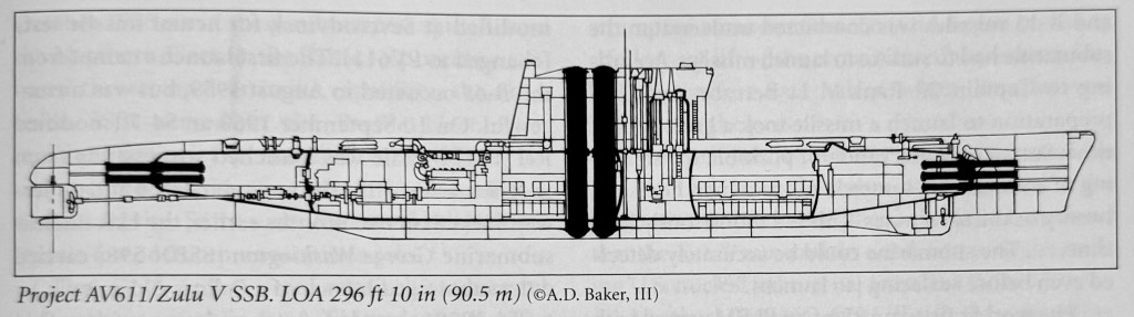
The Zulu-class B-67 (Project 611) was modified at Molotovsk (Severodvinsk) shipyard to become the first ballistic missile-carrying submarine in the world. The sail was enlarged to house two R-11FM missile tubes, and it successfully fired the first ballistic missile from a submarine on 16 September 1955.60
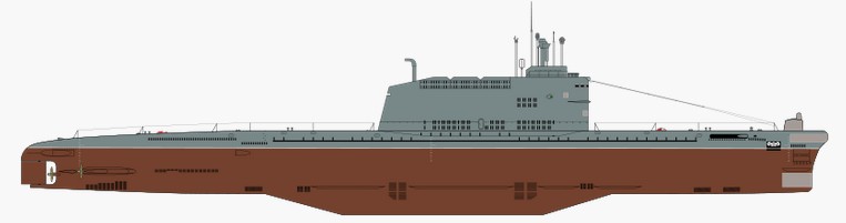
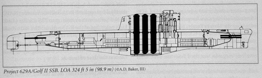

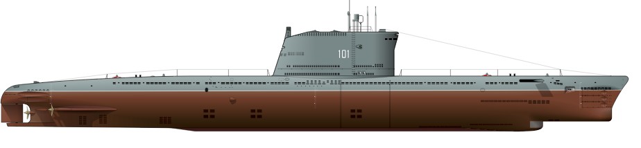
Twenty-two Golf-class (Project 629) submarines were constructed at Severodvinsk and Komsomol’sk-on-Amur between 1959 and 1962. They utilized the same diesel-electric machinery as the earlier Foxtrot-class (Project 641) attack boats, but had a larger surface displacement of 2,850 tons. These submarines carried three R-13 missiles inside tubes that were housed in the sail and extended through both the top and bottom of the pressure hull. In order to fire their missiles, the submarines had to surface, and the missiles had to be elevated out of the tubes prior to firing. This was particularly difficult in rough seas. One officer, Captain 2nd Rank V.L. Berezovskiy, noted that preparing to launch a missile would involve surfacing, observing the position, and steadying the compasses. All of which could take around 1 hour and 30 minutes. Even then, there was the chance that the sub could be detected before surfacing. The first five of these boats were armed with the R-11FM missiles, but would later receive the R-13 missiles.62
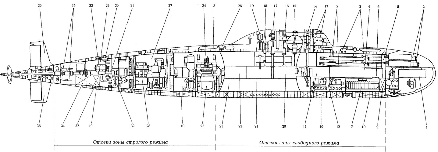
1. Yenisei HAC main antenna 2. 533 mm torpedo tubes 3. VVD system cylinders 4. First compartment (torpedo) 5. Spare torpedoes with automated loading complex 6. Sargan FCS equipment room 7. Air Bottles 8. Bubble-less torpedo firing tank 9. Bow trim tank 10. Central gas block 11. Second compartment (radio-electronic and auxiliary equipment) 12. VVD system compressor partition 13. Yenisei HAC antennas 14. Main periscope mast, Aiva communication antenna (satcom Molniya); 15. Pop-up external camera and TV-1 system periscope 16. Telescoping antennas, Chibis radar 17. Antenna mast for the Topol (Molniya satcom) 19. Veslo-P radio direction finder mast 20. Third compartment (main command post) 21. Main command post 22. Living, medical and sanitary rooms 23. Galley and provision chambers 24. Fourth compartment (reactor) 25. Reactor with steam generators, circulation pumps/biological protection tanks 26. Emergency buoy 27. Fifth compartment (turbine) 28. Block steam turbine plant 29. Sixth compartment (desalination plants and steering gears) 30. Stern hatch 31. Shaft line 32. Oil tanks 33. Desalination plant 34. Stern trim tank 35. Stern rudder drives 36. Stern vertical stabilizers.
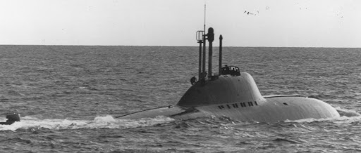
The Alfa-class (Project 705) submarines were designed with titanium hulls for high-speed ASW to attack Western missile and attack boats in Soviet defensive areas. With an endurance of around 50 days, their heavy automation resulted in the Alfas having extremely small crews of around 30 men, most of whom were officers. One notable feature was the sail being heavily blended into the hull of the submarine. The sail also possessed a unique feature, a first for a submarine: an escape chamber above the control room that could house the entire crew. With the crew inside, the escape chamber, with a part of the sail to provide buoyancy, would be released and ascend to the surface for rescue. This meant the crew wouldn’t be exposed to the cold water or pressure, and the chamber could shelter the crew when on the surface until rescue could arrive. The streamlined hull made the submarine very maneuverable and very fast, with a submerged speed of around 41 knots! That said, they were particularly noisy at high speeds, and while their titanium hulls were very strong, they didn’t possess a particularly deep test depth. (It’s thought that their test depth was only about 1,300 feet as opposed to the originally estimated 2,100 feet by Western intelligence. Roughly the same as a U.S. Thresher/Permit-class submarine.)63
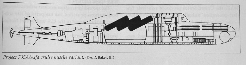
There was even an SSGN version of the Alfa-class submarines, which were never built. These featured an extended sail that housed six missile tubes at a fixed angle behind the periscopes and masts. These subs would carry the Amethyst/SS-N-7 antiship missile. Had these been built, they would likely have had a length of approximately 267 feet (81.4m) and displaced some 2,385 tons when surfaced.64
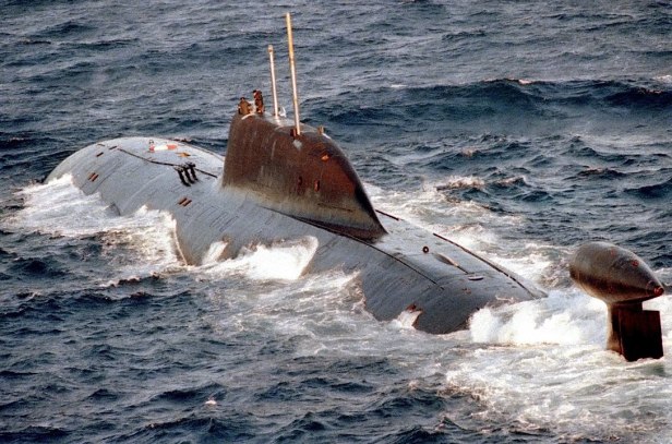
The highly streamlined sails of Soviet subs were repeated in a handful of later classes, such as the Victors, the Beluga (a research submarine similar to USS Albacore), and the later Akulas.


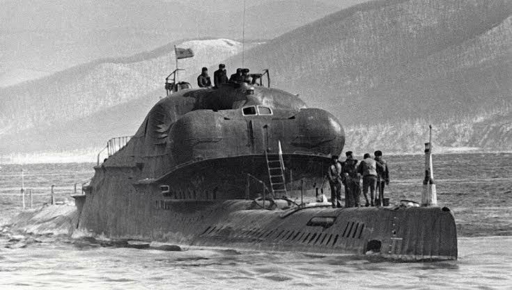
Not to be outdone by the U.S., the Soviet Union would produce six of the Typhoon-class (Project 941). These ballistic missile submarines were developed in response to the U.S. Ohio-class and were the largest submarines built by any nation in the world, displacing over 23,000 tons surfaced and some 48,000 tons submerged (nearly as much as the RMS Titanic). The sail structure of these submarines is absolutely massive, rising some 42.66 feet (13 m) above the waterline amidships to house the submarine’s masts and bridge. The sail sits atop a large, bulbous 98-foot-long and 19.66-foot-diameter pressure hull in the center of the vessel that bulges out above the two 488.75-foot-long pressure hulls (each some 23.66 feet in diameter). The central pressure hull below the sail contains the control room and command facilities. At the bottom of the sail on each side and outboard of the control room pressure hull are escape chambers for the sub’s crew.66
A Sailless Submarine?
In some ways, this begs the question: Does a submarine even need a sail? In some ways, no. Designs for sailless submarines have been contemplated, but none have gone beyond the conceptual stage.
To be clear, when referring to submarines in this instance, we’re talking about crewed underwater combat vessels capable of sustained independent operations, as opposed to submersibles, which require support vessels or Unmanned Underwater Vehicles (UUVs). The following will examine just a few ideas for sailless submarines that countries have come up with over the decades. Again, it’s not meant to be all-inclusive.
CONFORM
Short for Concept Formulation, CONFORM was one of the studies initiated by the U.S. Navy in the late 1960s as a follow-up to the Permit and Sturgeon classes. This submarine was envisioned to have an S5G Natural Circulation Reactor (NCR) inside a 4,800-ton (submerged) hull, roughly the size of a Sturgeon-class boat and capable of greater than 30 knots. Several innovative capabilities were examined, including the ability for the periscopes and masts to fold down into recesses in the hull rather than retracting vertically down into a sail and the pressure hull. This arrangement would have reduced pressure hull penetrations, created a more flexible internal arrangement, and likely eliminated the need for a sail altogether. After numerous iterations, however, Admiral Rickover used his influence to push Congress to accept the Los Angeles-class instead of CONFORM.67 CONFORM was ultimately abandoned in 1969.68
Project 673
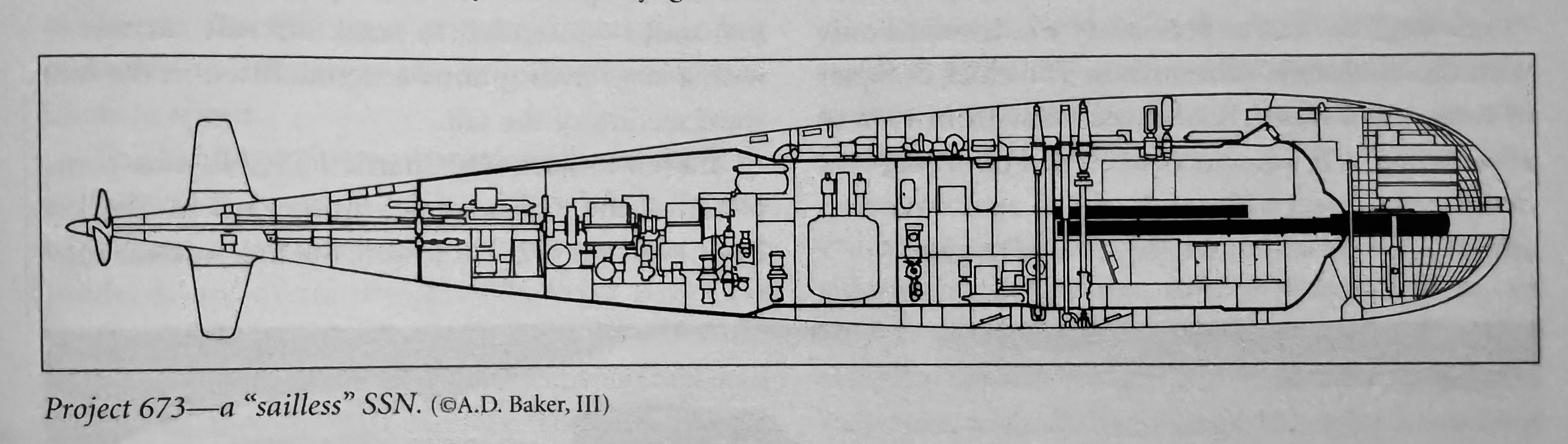
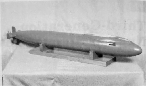
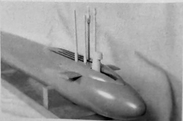
The Soviets had a similar design for a sailless submarine. The Victor-class (Project 671) attack subs turned out to be very successful, but had they not, alternative designs were conceived. One such design was Project 673. Developed by SBD-112 in 1960, this was to be a small nuclear-powered attack boat with a small surface displacement, possibly as small as 1,500 tons. The design envisioned a single reactor plant producing some 40,000 hp with a max speed of 35 – 40 kts. A faster version would have no sail.71 Conceptual drawings were created, but this submarine never went beyond that stage. In the end, the sailless version, while likely to be very fast, turned into a rather ugly tadpole-shaped vessel. Like other Soviet submarines of the time, they likely would’ve also been fairly loud at high speeds and easy for sonar to detect.
Chinese 2018 “Sailless Submarine”
The title is something of a misnomer, but in October 2018, the People’s Republic of China came very close to a sailless submarine when it launched the first submarine with barely any sail. However, if you look closely, it technically does have a sail. It’s just a really small hump amidships, likely just to cover the mast tops.
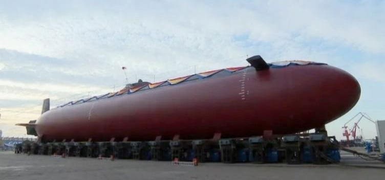
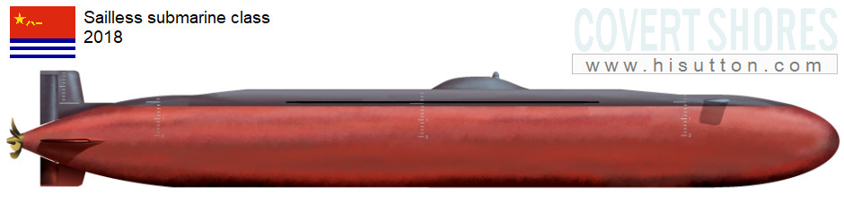
The exact design and purpose of this submarine are unclear, but it’s estimated to be about 150 feet long and 15 feet wide.72 Naval analyst HI Sutton speculates that it likely does have a crew and isn’t a large test concept for an Unmanned Underwater Vehicle (UUV) as was previously thought. It also appears to lack a snorkel system, so it may use all-electric battery propulsion or Air-Independent Propulsion (AIP), and there’s no indication of torpedo tubes or a sonar dome. Sutton writes that this is most likely a research submarine or a technology test bed for future subs.73
Inflatable Sails?
While not sailless, per se, the idea of a smaller or reduced sail for submarines is still floating around the U.S. Navy today. Defense writer Thomas Newdick at The War Zone writes that the U.S. Navy is investigating the possibility of submarines using an Inflatable Deployable Sail System (IDSS). This system would stow (i.e., deflate) the sail when the boat is submerged, but inflate it when it’s required. The primary purpose of this system is to increase the sub’s maneuverability, speed, and acoustic stealth.74
The challenge with the IDSS is how to safely navigate the submarine from the sail when it’s surfaced. The article notes that the inflatable sail wouldn’t house any sensors (presumably the sub’s masts), which would instead be housed in the hull. NAVSEA specifications note the inflatable sail would instead have a “bridge module” made of either a rigid or “hybrid rigid” material, weighing not more than 4,000 pounds, capable of operating in icy waters, and with ballistic protection from small arms fire. The bridge module would accommodate a cockpit with space for four, a flip-up windshield, storage lockers, any required communications and lighting, with ladders to allow access to the bridge. Additionally, NAVSEA specified that the inflatable sail have a minimum of 16 feet of freeboard, be capable of 10,000 operational cycles, deploy/retract within one minute using pressurized seawater or air, maintain its shape while at periscope depth, be operable in Sea State 6, and in temperatures from -40 to 150 degrees Fahrenheit. To achieve these parameters, it’s thought that the IDSS could be constructed of any number of synthetic fibers, such as Kevlar, Vectran, DSP (Dimensionally Stable Polyester), PEN (polyethylene napthalate), and Spectra, a type of ultra-high molecular weight polyethylene. Of course, this inflatable sail is quite a way off and presents the challenge of creating a reliable system. Should the sail fail to deploy or retract, it could leave the submarine extremely vulnerable.75 Based on this article, it seems that the only purpose of the inflatable sail would be to temporarily house a bridge structure.
To Sail or Not to Sail?
The purpose of a submarine’s sail hasn’t changed much since they evolved from the fairwater superstructures of WWII subs. However, we’ve seen that the shape and contents of the sail can vary drastically depending on the design of the submarine and the country’s requirements. U.S. submarine sails have always traditionally housed the bridge cockpit and masts, whereas the Soviets experimented with a variety of superstructures that housed everything from masts to missile tubes and escape chambers. Designs from sailless submarines have been contemplated, but none have thus far been fully realized. The closest has been the People’s Republic of China in 2018 with their nearly sailless submarine. Even then, the future of the sail is somewhat in question as the U.S. Navy experiments with the possibility of fitting future submarines with inflatable sails. Time will see what new designs people come up with and how submarines will change shape in the coming decades.
Notes
- I do have a rather amusing story from a submarine captain who managed to use his submarine’s sail as an actual sail…of sorts. That’s for another time. ↩︎
- Robert Hutchinson, Jane’s Submarines: War beneath the Waves from 1776 to the Present Day, Paperback ed (HarperCollins, 2003), 8 – 10. ↩︎
- Robert Hutchinson, Jane’s Submarines: War beneath the Waves from 1776 to the Present Day, Paperback ed (HarperCollins, 2003), 10. ↩︎
- Jesse Beckett, “A Submarine Made It Home with a Sail Made of Blankets | War History Online,” Warhistoryonline, August 11, 2021, https://www.warhistoryonline.com/war-articles/submarine-made-it-home-with-sail-made-of-blankets.html. USS Conestoga was eventually located off the coast of California in 2009 and positively identified in 2015. ↩︎
- U.S. Naval Historical Center Photograph NH 102849. ↩︎
- Jesse Beckett, “A Submarine Made It Home with a Sail Made of Blankets | War History Online,” Warhistoryonline, August 11, 2021, https://www.warhistoryonline.com/war-articles/submarine-made-it-home-with-sail-made-of-blankets.html. ↩︎
- US Naval Historical Center. ↩︎
- Jesse Beckett, “A Submarine Made It Home with a Sail Made of Blankets | War History Online,” Warhistoryonline, August 11, 2021, https://www.warhistoryonline.com/war-articles/submarine-made-it-home-with-sail-made-of-blankets.html. ↩︎
- Jesse Beckett, “A Submarine Made It Home with a Sail Made of Blankets | War History Online,” Warhistoryonline, August 11, 2021, https://www.warhistoryonline.com/war-articles/submarine-made-it-home-with-sail-made-of-blankets.html. ↩︎
- Theodore Roscoe, United States Submarine Operations in World War II, 4th print (Naval Institute Press, 1954), 15. ↩︎
- Norman Friedman, U.S. Submarines through 1945: An Illustrated Design History, (Annapolis, Maryland: Naval Institute Press, 1995), 9. ↩︎
- Friedman, U.S. Submarines through 1945, 178. ↩︎
- Friedman, U.S. Submarines through 1945, 244. ↩︎
- Friedman, U.S. Submarines through 1945, 246. ↩︎
- Stefan Terzibaschitsch, Submarines of the US Navy, trans. M.J. Shields (Arms and Armour Press [u.a.], 1991), 141. ↩︎
- GUPPY is an acronym for Greater Underwater Propulsion Program, with the Y added to make it more pronounceable. ↩︎
- Terzibaschitsch, 140. ↩︎
- Terzibaschitsch, 159. ↩︎
- Friedman, U.S. Submarines through 1945, 36. ↩︎
- Norman Polmar and K.J. Moore, Cold War Submarines: The Design and Construction of U.S. and Soviet Submarines. 1. ed. (Dulles, Va.: Potomac Books, 2005), 15. ↩︎
- Friedman, U.S. Submarines through 1945, 37. ↩︎
- Friedman, U.S. Submarines through 1945, 50. ↩︎
- Friedman, U.S. Submarines through 1945, 51. ↩︎
- Friedman, U.S. Submarines through 1945, 241 – 242. ↩︎
- Friedman, U.S. Submarines through 1945, 18 – 19. ↩︎
- Norman Friedman, U.S. Submarines since 1945: An Illustrated Design History, Revised edition. Printed case edition, with Jim Christley (Naval Institute Press, 2023), 26. ↩︎
- Stefan Terzibaschitsch, Submarines of the US Navy, trans. M.J. Shields (Arms and Armour Press [u.a.], 1991), 112 – 115. In contrast to Friedman, Terzibaschitsch refers to the superstructure as a conning tower, but notes that it would later be called a “sail.” ↩︎
- Polmar and Moore, Cold War Submarines, 17. ↩︎
- Friedman, U.S. Submarines since 1945, 30. ↩︎
- Friedman, U.S. Submarines since 1945, 51. ↩︎
- Friedman, U.S. Submarines since 1945, 45 & 94. ↩︎
- Friedman, U.S. Submarines since 1945, 95. ↩︎
- Friedman, U.S. Submarines since 1945, 96. ↩︎
- Friedman, U.S. Submarines since 1945, 98. ↩︎
- Friedman, U.S. Submarines since 1945, 96 – 98. ↩︎
- Polmar and Moore, Cold War Submarines, 66. ↩︎
- Friedman, U.S. Submarines since 1945, 97. ↩︎
- Polmar and Moore, Cold War Submarines, 67. ↩︎
- Friedman, U.S. Submarines since 1945, 35. ↩︎
- Friedman, U.S. Submarines since 1945, 52. ↩︎
- Friedman, U.S. Submarines since 1945, 57. ↩︎
- Photo credit: Dmoore5556 – Own work, CC BY-SA 4.0, https://commons.wikimedia.org/w/index.php?curid=68159961. ↩︎
- Friedman, U.S. Submarines since 1945, 150. ↩︎
- Friedman, U.S. Submarines since 1945, 130. ↩︎
- Polmar and Moore, Cold War Submarines, 151. ↩︎
- Polmar and Moore, Cold War Submarines, 64. ↩︎
- Polmar and Moore, Cold War Submarines, 64. ↩︎
- Polmar and Moore, Cold War Submarines, 154. ↩︎
- Photo credit: USN photo # N-4482V-005, by Photographer’s Mate Second Class Steven H. Vanderwerff. ↩︎
- The U.S. Coast Guard procures several custom-designed Special Purpose Craft to carry out operations that are unsuitable for the standard response boats. In this case, these boats have seating for 10 in the pilothouse, a small mess deck, and berthing for five crew. ↩︎
- Photo credit: USN photo # N-6107B-001 by Sonar Technician 2nd Class Will Blackshear. ↩︎
- Polmar and Moore, Cold War Submarines, 93-94. In contrast, U.S. submarines stored missiles in a hangar, which were then extracted and placed on launching rails on deck for firing. ↩︎
- Norman Polmar, The Naval Institute Guide to the Soviet Navy, 5. ed (Naval Institute Press, 1991), 391. ↩︎
- Polmar and Moore, Cold War Submarines, 94 – 95. ↩︎
- Polmar and Moore, Cold War Submarines, 97 – 98. ↩︎
- Copyright: © IWM. Original Source: http://www.iwm.org.uk/collections/item/object/205302969. ↩︎
- Polmar and Moore, Cold War Submarines, 101. The standard Mk. 44 and Mk. 46 anti-submarine warfare torpedoes couldn’t attack surface targets, including surfaced subs. ↩︎
- Polmar and Moore, Cold War Submarines, 95. ↩︎
- Polmar and Moore, Cold War Submarines, 109. ↩︎
- Polmar and Moore, Cold War Submarines, 107 – 09. ↩︎
- Polmar and Moore, Cold War Submarines, 109. ↩︎
- Polmar and Moore, Cold War Submarines, 107 – 110. ↩︎
- Polmar and Moore, Cold War Submarines, 140 – 144. ↩︎
- Polmar and Moore, Cold War Submarines, 163. ↩︎
- Polmar and Moore, Cold War Submarines, 163. ↩︎
- Polmar and Moore, Cold War Submarines, 194 – 195. ↩︎
- Polmar and Moore, Cold War Submarines, 267 – 70. ↩︎
- Friedman, U.S. Submarines since 1945, 166. ↩︎
- Polmar and Moore, Cold War Submarines, 268. ↩︎
- Polmar and Moor, Cold War Submarines, 161. ↩︎
- Polmar and Moore, Cold War Submarines, 161. ↩︎
- H.I. Sutton, “The Chinese Navy’s New Mystery Submarine,” Forbes, October 9, 2019, https://www.forbes.com/sites/hisutton/2019/10/09/china-navy-new-mystery-submarine/. ↩︎
- H.I. Sutton, “China Sailless Submarine,” Covert Shores, October 8, 2019, http://www.hisutton.com/China_Sailless_Submarine.html. ↩︎
- Thomas Newdick, “The Navy Is Looking At Fitting Its Future Attack Submarines With Inflatable Sails,” The War Zone, July 20, 2021, https://www.twz.com/41614/the-navys-future-attack-submarines-may-be-fitted-with-inflatable-sails. ↩︎
- Thomas Newdick, “The Navy Is Looking At Fitting Its Future Attack Submarines With Inflatable Sails,” The War Zone, July 20, 2021, https://www.twz.com/41614/the-navys-future-attack-submarines-may-be-fitted-with-inflatable-sails. ↩︎
Bibliography
Beckett, Jesse. “A Submarine Made It Home with a Sail Made of Blankets | War History Online.” Warhistoryonline, August 11, 2021. https://www.warhistoryonline.com/war-articles/submarine-made-it-home-with-sail-made-of-blankets.html.
Friedman, Norman. U.S. Submarines since 1945: An Illustrated Design History. Revised edition. Printed case edition. Annapolis, Maryland: Naval Institute Press, 2023.
Friedman, Norman. U.S. Submarines through 1945: An Illustrated Design History. Naval Institute Press, 1995.
Hutchinson, Robert. Jane’s Submarines: War beneath the Waves from 1776 to the Present Day. Paperback ed. HarperCollins, 2003.
Newdick, Thomas. “The Navy Is Looking At Fitting Its Future Attack Submarines With Inflatable Sails.” The War Zone, July 20, 2021. https://www.twz.com/41614/the-navys-future-attack-submarines-may-be-fitted-with-inflatable-sails.
Polmar, Norman. The Naval Institute Guide to the Soviet Navy. 5. ed. Naval Institute Press, 1991.
Polmar, Norman, and Kenneth J. Moore. Cold War Submarines: The Design and Construction of U.S. and Soviet Submarines. 1. ed. Dulles, Va.: Potomac Books, 2005.
Roscoe, Theodore. United States Submarine Operations in World War II. 4th print. Naval Institute Press, 1954.
Sutton, H.I. “China Sailless Submarine.” Covert Shores, October 8, 2019. http://www.hisutton.com/China_Sailless_Submarine.html.
Sutton, H.I. “The Chinese Navy’s New Mystery Submarine.” Forbes, October 9, 2019. https://www.forbes.com/sites/hisutton/2019/10/09/china-navy-new-mystery-submarine/.
Terzibaschitsch, Stefan. Submarines of the US Navy. Translated by M.J. Shields. Arms and Armour Press [u.a.], 1991.
